








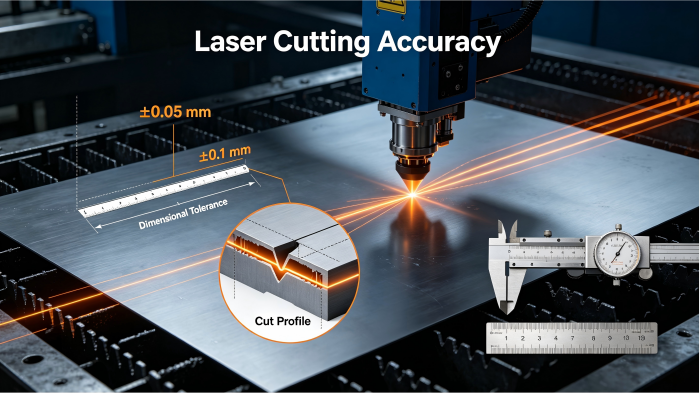
For mechanical engineers and procurement professionals, determining whether a ±0.05 mm dimensional callout is achievable with fiber laser cutting—or if CNC milling is required—has always been a balancing act between design requirements and production costs. Estimating process precision benchmarks based solely on experience often leads to deviations: overly loose tolerances cause excessive assembly gaps and fit failures, while unnecessarily tight tolerances drive production costs up dramatically.
Based on mass production measurement data from a vast number of precision sheet metal components, PartsMastery has compiled the actual dimensional deviation patterns across different materials and plate thicknesses. This comprehensive laser cutting tolerance reference chart and Design for Manufacturing (DFM) guidelines help you quickly validate the manufacturability of your CAD drawings and avoid disconnects between design and production.
Standard Baseline Tolerances for Laser Cutting
When no specific dimensional deviation is explicitly noted on a CAD drawing, manufacturers follow widely accepted international standards for processing. The most widely applied general tolerance standard in laser cutting is DIN ISO 2768. Professional sheet metal fabricators including PartsMastery default to ISO 2768-1 class m (medium) for all laser-cut sheet metal parts unless otherwise specified.
Below are the laser cutting tolerance values corresponding to ISO 2768-1 class m, with reference values for class f (fine) precision also included:
| Nominal Dimension Range (mm) | Standard Class (m-class) Tolerance (mm) | Precision Class (f-class) Tolerance (mm) |
|---|---|---|
| <0.5 | ±0.10 | ±0.10 |
| 0.5 – 3 | ±0.10 | ±0.05 |
| 3 – 6 | ±0.20 | ±0.10 |
| 6 – 30 | ±0.30 | ±0.15 |
| 30 – 120 | ±0.50 | ±0.20 |
| 120 – 400 | ±0.80 | ±0.30 |
| 400 – 1000 | ±1.20 | ±0.50 |
For conventional sheet metal projects, typical laser cutting tolerances for linear dimensions under 100 mm can be stably controlled within ±0.1 mm to ±0.2 mm, meeting the assembly requirements of most commercial products. For ultra-high precision scenarios, fine-class tolerances can tighten accuracy down to ±0.05 mm, but this grade requires high-end fiber laser equipment and optimal process parameters with strict quality control to achieve.
How Material Thickness Affects Cutting Tolerances
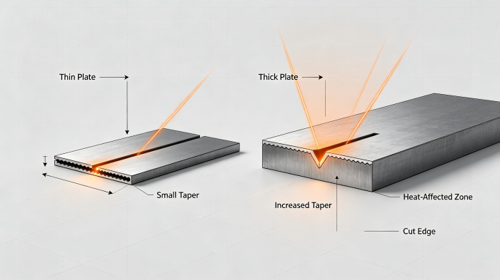
Laser cutting tolerance is not a fixed value, but a dynamic range that increases positively with plate thickness. The thicker the material, the more pronounced the laser beam diffusion effect, and the wider the heat-affected zone (HAZ) generated during cutting. This creates a slight angle on the cut edge, commonly known as kerf taper in the industry.
The DIN EN ISO 9013-1 standard specifies thermal cutting tolerance grades for plates of different thicknesses. Taking fiber laser processing as an example, the cutting tolerance of a 1 mm thick stainless steel part is naturally far tighter than that of a 15 mm thick carbon steel plate. For steel plates with a thickness of 0–25 mm, the allowable dimensional deviation gradually widens from ±0.075 mm up to ±3.25 mm.
Therefore, at the design stage, tolerance requirements must be relaxed accordingly as material thickness increases. Specifying accuracy without considering plate thickness has no practical engineering significance.
Raw Material Inherent Tolerances: An Overlooked Precision Variable
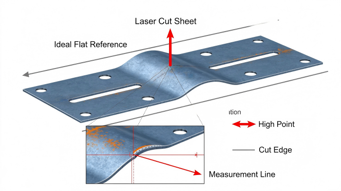
Many engineers overlook a core premise during design: sheet metal raw materials inherently have physical deviations. Before the laser even starts processing, the material already carries baseline tolerances—perfectly flat metal sheets do not exist in reality.
According to the DIN EN 10259 standard, standard cold-rolled steel sheets have specified flatness tolerance requirements. For example, a 2.0 mm thick cold-rolled steel sheet naturally has a flatness variation of ±0.10 mm. If the profile tolerance specified in the design is smaller than the inherent flatness tolerance of the raw material, the part will fail quality inspection no matter how precise the cutting process is.
DFM Design Rules for Laser-Cut Hole Tolerances
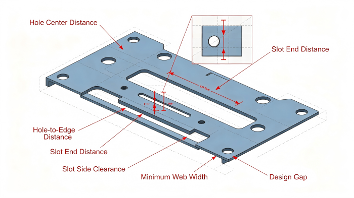
When designing hole and slot features for laser cutting, reasonable safety clearances must be reserved to ensure structural stability and dimensional accuracy of the part. If holes are placed too close to the sheet edge, concentrated heat during cutting will cause local material deformation, directly compromising hole diameter tolerance and geometric accuracy.
Here are three general rules of thumb for design, covering most conventional processing scenarios:
- The minimum hole diameter should match the material thickness at a 1:1 ratio.
- The distance from the center of a hole to the edge of the plate should be at least 1 times the hole diameter.
- For slot features, the distance to the plate edge should be at least 1.5 times the slot width.
In addition, to maintain stable overall part tolerances, the width of web material (the material between two cut features) should never drop below 50% of the material thickness.
You can upload your STEP or DXF drawings to PartsMastery’s AI-powered platform. The system will instantly generate a manufacturability analysis report that automatically identifies the spacing violations above and other design risks.
Balancing Tolerance and Cost: Avoid Over-Tolerancing
Applying blanket ultra-tight tolerance callouts across an entire drawing is a very common engineering design mistake. High precision requirements force significantly reduced cutting speeds, directly lowering equipment throughput. They also require professional inspection equipment such as Coordinate Measuring Machines (CMMs) to verify positional tolerances, raising quality control costs accordingly.
Combined, indiscriminate tolerance tightening can increase overall production costs by 300% to 500%. The correct design approach is to apply strict tolerances only to critical mating surfaces and functional assembly points, and use standard laser cutting tolerances for all non-critical contours. This maximizes cost control while ensuring functional performance.
Precision Capabilities of Different Cutting Equipment
The type of processing equipment directly determines the final accuracy limit of parts. During design, accuracy requirements must be matched to the capabilities of the corresponding process to avoid demands that exceed process boundaries.
- Fiber laser cutters: The current mainstream equipment for metal sheet processing, with an extremely small focused spot size and high cutting efficiency. For common metals such as aluminum alloy and stainless steel, they can consistently achieve cutting tolerances of ±0.05 mm to ±0.2 mm.
- CO₂ laser cutters: More suitable for processing thick carbon steel, wood, plastics and other materials, with a wider material compatibility but slightly lower accuracy. Their cutting tolerances typically range from ±0.1 mm to ±0.5 mm.
मुख्य बिंदु
Setting reasonable laser cutting tolerances both controls production costs effectively and ensures parts fit perfectly on the assembly line. For general dimensions, prioritize design based on ISO 2768-m class; for thicker plate parts, relax deviation requirements accordingly. Unless functionally necessary, do not demand CNC-level precision from a thermal cutting process.
If you have CAD drawings ready for production, you can upload them to the PartsMastery platform. The system’s automated quoting engine will analyze part geometry, deliver an accurate quote within minutes, and generate a complete DFM analysis report to ensure your tolerance design is production-ready.
अक्सर पूछे जाने वाले प्रश्न
What are the standard tolerances for laser cutting?
For conventional structural parts and sheet metal components, the industry-standard baseline tolerance is ±0.127 mm (±0.005 inches), which meets the needs of most commercial products made of metal and plastic.
Can laser cutting achieve ±0.05 mm tolerances?
Yes. Under optimal process conditions, modern high-power fiber laser equipment can consistently achieve ±0.05 mm accuracy on thin metal sheets. This precision grade reduces cutting speed and raises quality control requirements, so per-part production costs will increase accordingly.
What is the difference in tolerance levels between laser cutting and CNC machining?
CNC machining is a mechanical subtractive process with higher rigidity and controllability, and can easily achieve machining accuracy of ±0.01 mm. Laser cutting is a thermal process focused on efficient, low-cost fabrication of flat parts, with typical accuracy in the ±0.1 mm range. The two processes serve different application scenarios.