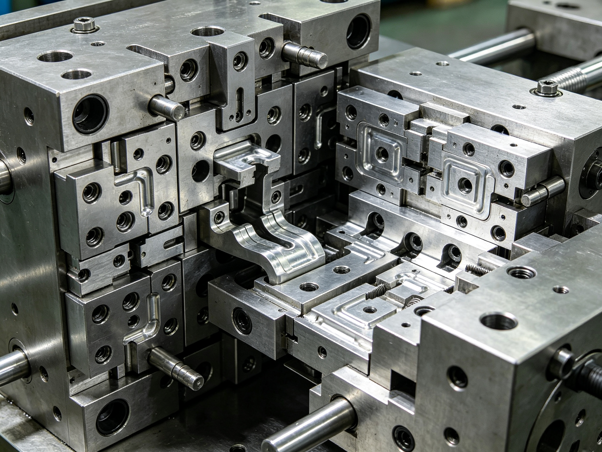
A progressive die ranks among the most cost-effective production tools in manufacturing, yet it also stands as one of the most expensive investments when built incorrectly. Manufacturers custom-design it for a single part geometry, so the “does it fit” question requires a clear answer before anyone cuts the die steel, not after the tool already exists.
When engineers select the right application, per-part cost drops to a level that few processes can match. When they choose wrongly, the investment sits on the project ledger for years. Whether your part qualifies for progressive die stamping depends on how the process works and where its real boundaries lie. This guide starts from process principles and systematically analyzes the applicable conditions, cost logic, geometric limitations, and decision path of progressive die stamping, helping engineers make the right judgment before committing to tooling.
1. How Progressive Die Stamping Works
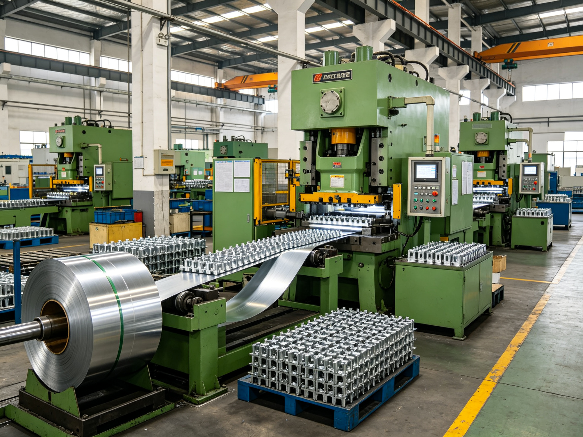
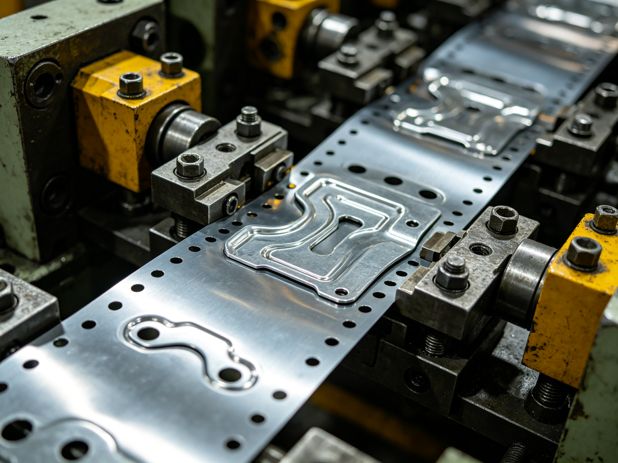
Progressive die stamping feeds a strip of metal from a coil through a single die that contains many stations. Each press stroke advances the strip by one pitch, and each station performs one operation: piercing, blanking, bending, forming, coining, or trimming. The part stays attached to the strip through a carrier web until the final station cuts it free. One stroke produces one finished part.
This carrier web explains the core logic behind every selection criterion that follows. Because the part must remain connected, supported, and precisely located throughout its entire travel, the strip serves as both the part carrier and the alignment reference. Registration comes from pilot holes punched in the strip, not from manual operator adjustment.
The practical implication is straightforward: if a part can ride the strip through all stations without distorting or losing support, progressive die stamping can usually produce it. If it cannot stay on the strip, no production volume can solve this fundamental problem.
2. Volume and Design Stability: The Real Payback Question
In a progressive die stamping program, the tool represents the dominant upfront cost, and manufacturers pay it only once. The logic that recovers it is the difference between progressive per-part cost and the cost of a tool-free route, multiplied by every part that runs. This logic points to two conditions that must hold together.
2.1 High and Sustained Annual Volume
The first condition is high and sustained annual volume. Tooling amortizes across hundreds of thousands of parts per year, and a program life of several years represents the common territory where the math works. The exact crossover point depends on part complexity, material, and piece price, so engineers should treat this range as a starting framework rather than a hard rule.
2.2 Frozen Design
The second condition is design stability, which engineers often overlook. If the drawing still changes, each revision can mean rework on the strip layout or the die itself, and that cost runs far higher than revising a laser-cut part. A progressive die rewards a frozen design. Volume without a design freeze carries almost as much risk as low volume.
Red flags at this gate are clear: prototype runs, first-pass validation, or annual demand that nobody can confirm. If the program is still finding its design or its volume, committing to progressive tooling is premature.
3. Can the Strip Carry Your Part?
Geometry screening is the second gate, and it filters out parts no matter how high the volume is. A progressive die needs the part to stay flat and stable on the strip while stations work on it. Engineers should think in terms of what the strip can hold, not what a press can form.
3.1 Suitable Part Characteristics
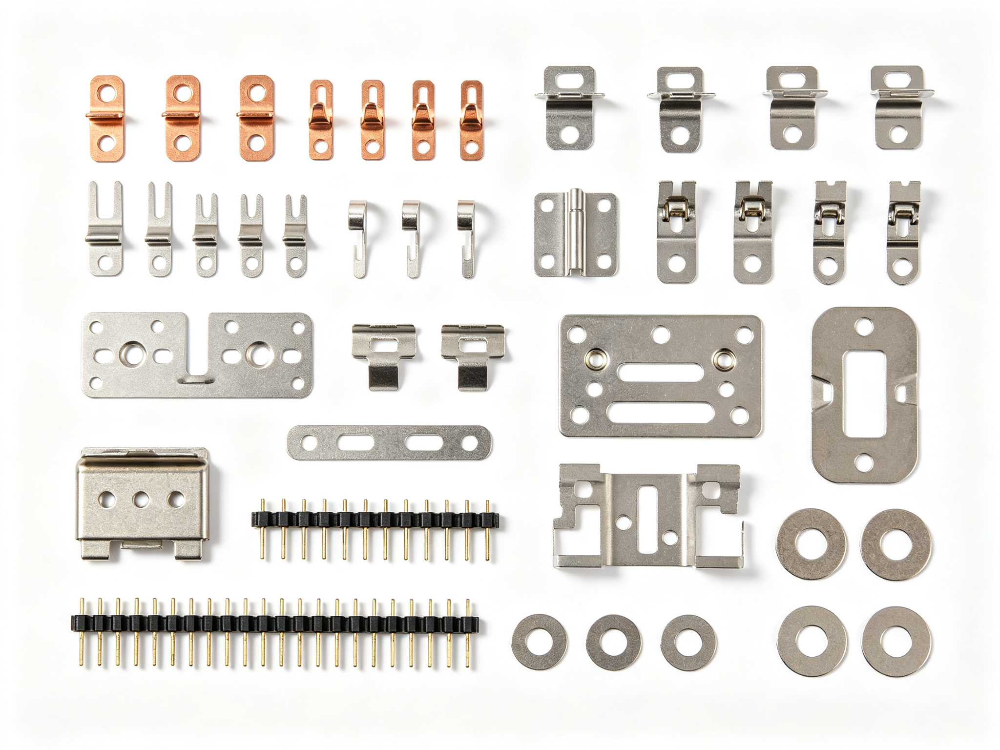
Good candidates are typically compact with shallow forming. Terminals, clips, brackets, contacts, shields, and washers built from holes, tabs, bends, and shallow forms travel well on the strip, especially when designers lay out features so the strip keeps a strong web between them.
3.2 Three Unsuitable Geometry Types
Red flags fall into three groups. First are deep draws. Cups and shells need material to flow into a cavity from all sides, which a carrier web cannot feed the way a dedicated deep drawing process can. Second are very large panels and heavily three-dimensional forms. They tend to overload the carrier or distort during forming. Third are thick-to-thin section changes. The strip loses support where the cross-section jumps.
For these parts, a transfer die is usually the better tool. A transfer die releases the blank early and moves it station to station through the process.
3.3 Surface Condition Check
One more check belongs in this gate: surface condition. The carrier web leaves small marks where the part breaks off, and forming stations can leave witness lines. If the part has a cosmetic surface that cannot show these marks, designers must hide them by design or remove them in a secondary operation. This is not a deal-breaker, but it belongs in the decision, not something discovered after the tool is built.
4. How Part Specifications Affect the Tool
The same geometry can produce very different dies depending on what the print specifies. Three specification areas move the tool cost and design the most.
4.1 Material Choice
The strip must be available in coil form and formable at the required thickness. Low-carbon steel, stainless, aluminum, brass, and copper all stamp routinely, but each changes the die. Stainless work-hardens and accelerates tool wear. Aluminum brings springback and surface-marking behavior. High-strength steel needs more tonnage and harder tooling. None of these disqualify a part. They are design inputs that a capable toolmaker accounts for in clearance, die steel selection, and surface treatment.
4.2 Tolerance Requirements
Progressive die stamping holds tolerances repeatably because registration is fixed in the tool, not in the operator. Tight tolerances are achievable, down to as tight as ±0.025 mm, but manufacturers buy them with more stations, finer tooling, and stricter maintenance. The engineering rule is to specify tight tolerance only where function demands it, on assembly datums and mating features, and leave the rest at standard stamping tolerance. Every unnecessary tight call adds cost to the tool without adding value to the part.
4.3 Finish and Secondary Operations
Plating, passivation, deburring, heat treatment, tapping, and assembly features all happen after stamping. They affect the die decision because they can change strip layout, part orientation, and process sequence. If a surface must be cosmetically clean, the carrier-break marks mentioned earlier have to be positioned or finished away. Teams should state secondary requirements before tooling review, not after the strip layout is locked.
5. When Another Route Fits Better
Progressive dies are the right answer for a specific window: high volume, stable design, strip-friendly geometry. Outside that window, other routes often beat it on total cost or lead time. The table below gives the common decision paths.
The low-volume row deserves emphasis. Running early batches by laser cutting and press brake, a sheet metal fabrication route, is often the cheapest way to validate fit, function, and assembly before a progressive die exists. Many programs should spend a few hundred parts proving the design this way. Once the drawing and the demand are both stable, committing to progressive tooling makes sense.
6. Decision Path: Screen, Validate, Commit
Put the gates together and the path has four steps. Run them in order and each one prevents a more expensive mistake later.
Confirm volume and freeze the design. The gate from the volume section applies unchanged: sustained annual demand and a drawing that is not changing. If either is missing, the decision stops here.
Screen the geometry. Run the strip-carry check from the geometry section: shallow forming, strong carriers, and cosmetic surfaces accounted for. If the part cannot ride the strip, transfer die stamping or another route takes over.
Validate on a low-risk route. Use laser cutting with press brake, or short-run tooling, to verify dimensions and assembly before spending on the production die. Prototype-stage iteration belongs here, not on the progressive tool.
Commit through a strip layout review. Before the die is released, the supplier should present a strip layout that shows the station sequence, carrier design, and scrap plan. That review, plus a DFM pass on the part, is where the final go/no-go is confirmed.
A complete RFQ makes steps 2 and 4 faster. Include: a 2D drawing with functional datums, material grade and temper with sheet thickness, annual volume and expected program life, cosmetic-surface and burr-side requirements, and a list of secondary operations. Suppliers can screen from a model alone, but the drawing closes the gaps.
7. PartsMastery Progressive Die Stamping Capabilities
PartsMastery provides professional progressive die stamping services covering the full range of metal stamped parts from terminals, clips, and brackets to shields, connectors, and precision hardware. The company is equipped with high-speed precision presses, a die design and manufacturing center, and complete secondary processing capabilities. These resources meet diverse needs from prototype validation to million-unit mass production.
In die design, the PartsMastery engineering team provides free DFM reviews and strip layout optimization services. Before committing to tooling, engineers carefully analyze the part’s geometric features, material properties, tolerance requirements, and secondary operations. They optimize station sequence, carrier design, and scrap plan to reduce tooling cost and production risk at the source. All dies use high-quality die steels and undergo strict heat treatment and surface treatment to ensure long life and stable stamping quality.
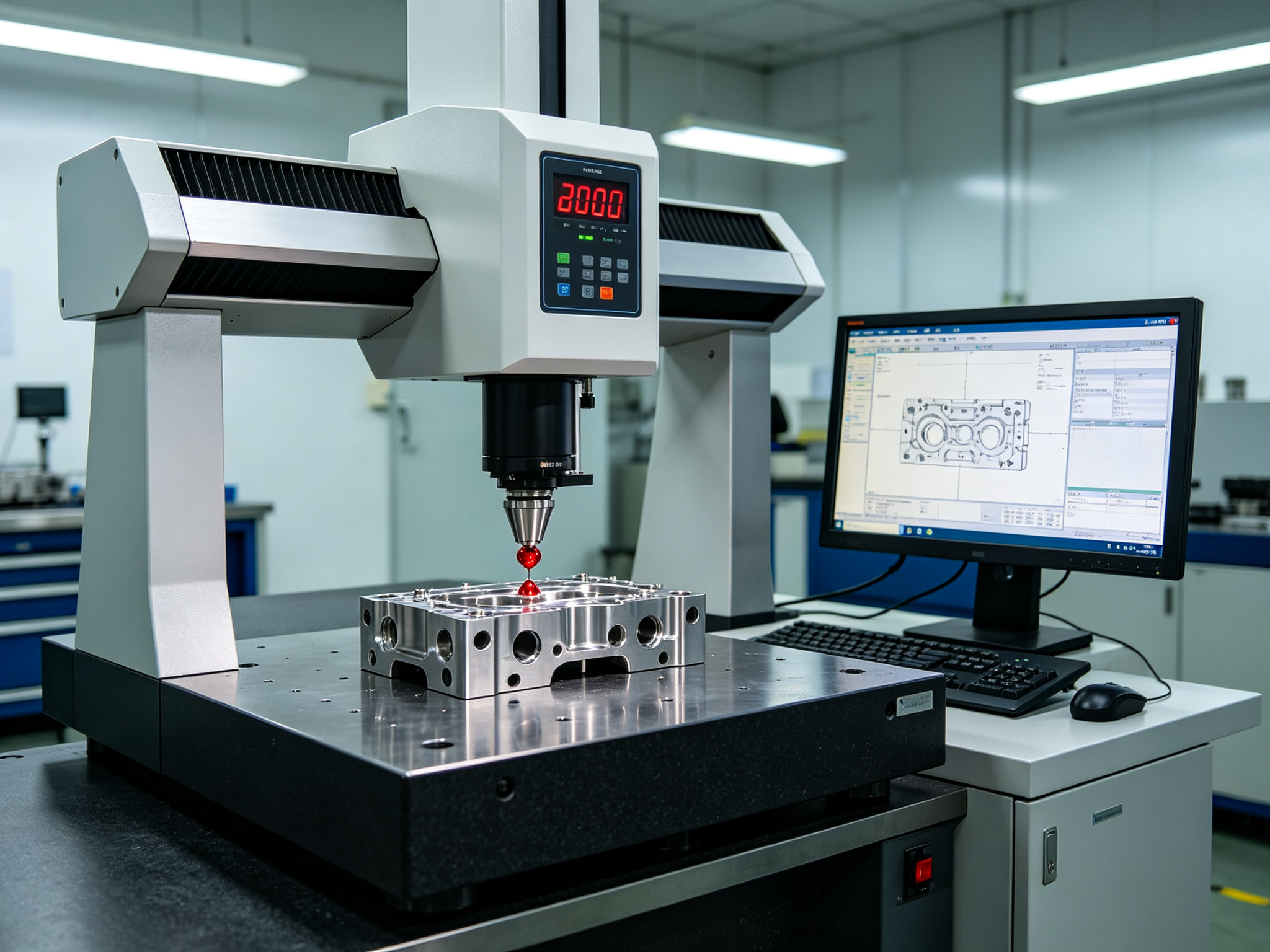
In quality control, PartsMastery has established a comprehensive inspection system equipped with coordinate measuring machines, vision measuring systems, height gauges, and hardness testers. From first article inspection to in-process patrol checks to outgoing full inspection, every stage follows strict quality standards and record traceability. All production batches carry complete material certificates, inspection reports, and batch traceability records, ensuring compliance with ISO 9001 and IATF 16949 quality system requirements.
Additionally, PartsMastery provides one-stop secondary processing services including plating, passivation, deburring, heat treatment, tapping, and assembly. Whether for simple flat stampings or complex multi-station formed parts, PartsMastery delivers complete solutions from die design and sample validation to batch production.
8. Summary
Whether progressive die stamping fits your part is decided by four checks in sequence: volume and design stability, strip geometry compatibility, the effect of materials and tolerances on the tool, and the availability of a cheaper validation route. When all four pass, progressive die stamping delivers a per-part cost that is hard to beat at production scale. When any one fails, another route almost always delivers better total value.
If your part looks like a fit, get the drawing in front of a stamping supplier before the design moves on. The right time is while the geometry is still cheap to change, not after the die steel is already cut. Through systematic selection evaluation and strip layout review, engineers can find the optimal balance between performance and cost and develop products that are both high-quality and commercially competitive.
Frequently Asked Questions
What annual volume makes progressive die stamping worthwhile?
Annual demand in the hundreds of thousands with a multi-year program is the common starting territory, but part complexity and material move the crossover. Ask the supplier to compare total cost, tooling amortized over the program life plus per-part cost, against a tool-free route. That comparison answers the question more reliably than any fixed number.
What drives the cost of a progressive die?
Station count is the largest driver; more operations mean a longer, more complex die with tighter carrier requirements. Tight tolerances, harder materials, and required die life add to it. So the strip layout, not the part size, is what a supplier actually prices.
How long does it take to build a progressive die?
Lead time scales with station count and complexity, typically several weeks to a few months. PartsMastery’s metal stamping service quotes progressive tooling with lead times starting around 20 days including the die for faster programs. Ask for the strip layout early; it determines the realistic schedule.
What maintenance does a progressive die need over its life?
Cutting edges wear and need sharpening, and wear changes burr size and dimensional drift over time. Plan scheduled maintenance and monitor critical dimensions between runs. A die that is maintained on a schedule holds tolerance far longer than one that only gets attention after a problem appears.