






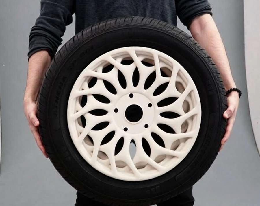
O mesmo modelo CAD pode ser produzido com várias tecnologias de impressão, mas nem todos os métodos produzem uma peça utilizável. Uma peça de resina com superfície lisa pode passar numa avaliação estética, mas apresentar resultados enganadores quando submetida a carga. Uma peça de nylon resistente pode passar nos testes funcionais, mas a rugosidade da sua superfície pode não estar à altura de um modelo destinado ao cliente.
A escolha do processo de impressão 3D adequado começa com a pergunta: “O que é que esta peça tem de demonstrar?” Em seguida, deve restringir as opções com base no material, na geometria, nos requisitos de superfície, na quantidade e no custo total de entrega. Esta abordagem é muito mais fiável do que escolher uma máquina com a qual já se está familiarizado ou partir do princípio de que a tecnologia mais recente é sempre a melhor.
1. Defina o objetivo para a fase em que se encontra atualmente
O mesmo projeto pode exigir um processo muito diferente em cada fase do desenvolvimento do produto. Defina a questão central que está a testar neste momento, em vez de tentar reproduzir todas as características do produto final no primeiro protótipo.
1.1 Validação do conceito e das dimensões
Os primeiros modelos conceptuais normalmente só precisam de confirmar as dimensões gerais, a forma e a ergonomia. Um acabamento de superfície de alta qualidade ou propriedades mecânicas próprias da produção aumentam os custos sem melhorar a tomada de decisão.
No caso de peças maiores com geometria relativamente simples, o FDM é frequentemente um ponto de partida económico. Verifique se as linhas de camada visíveis ocultam detalhes importantes e se as características de pequenas dimensões são reproduzidas com clareza suficiente para serem analisadas.
1.2 Ensaios de forma, ajuste e montagem
As peças utilizadas para a verificação da montagem requerem um controlo dimensional mais rigoroso. Identifique as superfícies de encaixe, a localização dos orifícios, as características dos elementos de fixação e as folgas antes de solicitar um orçamento.
Pode ser que a peça na sua totalidade não necessite de elevada precisão. Limitar os requisitos rigorosos às interfaces funcionais dá ao fornecedor mais margem para escolher um processo económico. Quando a superfície tal como foi impressa não consegue cumprir os requisitos de ajuste, a maquinagem dessa interface após a impressão é, muitas vezes, mais prática do que alterar todo o processo de fabrico.
1.3 Testes funcionais
Um protótipo funcional deve reproduzir as propriedades que estão a ser avaliadas. Comece pela direção real da carga e pela temperatura de funcionamento e, em seguida, verifique a presença de produtos químicos relevantes, humidade, radiação UV, impacto ou desgaste.
O nome do material, por si só, não é suficiente. Um fotopolímero descrito como “semelhante ao ABS”, por exemplo, não reproduz na íntegra o desempenho do ABS moldado. Se os resultados dos testes forem utilizados para aprovar um material de produção, confirme quais as propriedades que o substituto impresso pode e não pode reproduzir.
1.4 Avaliação estética
Os modelos estéticos dão maior importância aos detalhes, à textura, à cor, à transparência e às marcas de suporte visíveis. Os processos SLA ou PolyJet são, normalmente, um melhor ponto de partida do que os processos otimizados para peças funcionais duráveis.
O pós-processamento é igualmente importante. A resina SLA transparente pode necessitar de lixagem, polimento ou revestimento para apresentar um aspeto visualmente nítido. Não se deve partir do princípio de que a transparência de qualidade ótica é obtida logo à saída da impressora.
1.5 Utilização final ou produção em pequenas quantidades
As peças destinadas a utilização final impõem requisitos de repetibilidade, inspeção e documentação que não se aplicam a protótipos únicos. O processo escolhido deve garantir o cumprimento das dimensões críticas em todo o lote e oferecer um tipo de material adequado.
A quantidade também tem impacto na economia. Um processo que é eficiente para uma única peça pode não proporcionar o melhor custo unitário quando várias peças podem partilhar uma única plataforma de fabrico.
2. Um quadro prático para a seleção de processos
Um quadro de seleção eficaz elimina as opções inadequadas numa ordem fixa.
2.1 Começar pela família de materiais: polímero ou metal
A categoria do material é o primeiro critério de filtragem. Se a peça necessitar de metal por razões estruturais, térmicas, elétricas ou ambientais, a SLM (fusão seletiva a laser) poderá ser adequada para geometrias complexas que sejam difíceis de maquinar. Quando o projeto apresentar uma geometria maquinável e superfícies que exijam precisão crítica, a maquinação CNC deve continuar a ser considerada na comparação.
As peças de polímero oferecem uma gama mais ampla de opções. O processo FDM utiliza filamentos termoplásticos, enquanto os processos SLA e PolyJet utilizam fotopolímeros. Os processos SLS e MJF costumam fabricar peças a partir de pós de polímeros, como o nylon. A escolha do método adequado depende das propriedades do material que o teste deve reproduzir.
2.2 Dar prioridade à aparência ou ao desempenho
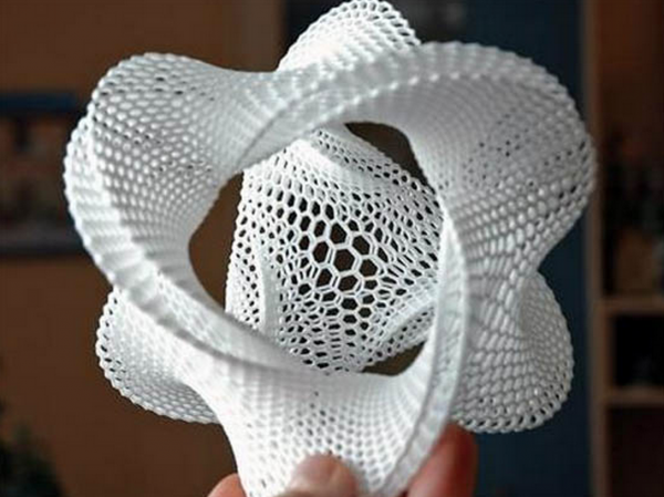
No caso de modelos visuais detalhados, a qualidade da superfície pode ser o principal critério de seleção. As tecnologias SLA e PolyJet são frequentemente utilizadas para superfícies lisas e detalhes finos. A tecnologia PolyJet destaca-se quando um modelo requer várias cores ou diferentes respostas simuladas dos materiais.
As peças funcionais em polímero requerem uma avaliação diferente. Dependendo do tipo de nylon, os métodos SLS e MJF são comuns para componentes complexos em nylon. O FDM industrial é adequado para peças de grandes dimensões, gabaritos, dispositivos de fixação e outras aplicações que requerem termoplásticos de engenharia.
Estas são orientações iniciais, não regras rígidas. A classe do material define o desempenho de referência. A orientação da impressão e o tamanho da peça determinam o grau de repetibilidade desse desempenho. As configurações da máquina e a capacidade do processo do fornecedor devem ser verificadas em relação aos requisitos críticos.
2.3 Análise das necessidades de assistência e remoção de pó
Processos como o FDM, o SLA, o PolyJet e o SLM podem exigir a utilização de suportes para determinados elementos. O contacto com os suportes pode deixar marcas, e as ferramentas de remoção necessitam de acesso físico à área suportada.
As tecnologias SLS e MJF utilizam o pó circundante para apoiar as peças durante a construção, o que permite a criação de geometrias complexas sem necessidade de suportes. No entanto, o pó residual tem de ser removido. Pode ser difícil, ou mesmo impossível, limpar completamente cavidades fechadas ou canais internos estreitos.
2.4 Confirmar a representatividade do material
Decida se o projeto necessita do material de produção exato ou apenas de um comportamento simulado. Um protótipo visual pode necessitar apenas da cor e do acabamento de superfície adequados, enquanto um ensaio de carga pode exigir uma rigidez definida, uma resposta ao impacto ou limites de temperatura.
Quando nenhum material impresso representa a peça de produção com precisão suficiente, os protótipos funcionais usinados por CNC podem proporcionar resultados de teste mais úteis.
2.5 Considerar a quantidade e a fase de produção
No caso de peças individuais, a preparação e o pós-processamento podem representar uma grande parte do custo total. Na produção em lote, a utilização da plataforma de impressão torna-se mais crítica. Os processos SLS e MJF permitem preencher um leito de pó com várias peças, enquanto a rentabilidade de outros processos depende mais da orientação das peças e da utilização de suportes.
O processo ideal pode variar entre a validação do conceito, a validação de engenharia e a produção de transição. Recorrer a tecnologias diferentes em cada fase é, normalmente, mais prático do que tentar que um único processo satisfaça todas as necessidades.
3. Associar cenários comuns ao processo adequado
As recomendações abaixo são pontos de partida, não regras rígidas. A escolha final depende, ainda assim, do tipo de material, do tamanho da peça, das condições de funcionamento e da capacidade do fornecedor.
| Cenário | Início recomendado | Por que é que isto faz sentido? | Verificações essenciais |
| Modelo-conceito de baixo custo | FDM | Económico para verificações básicas de geometria e dimensões | Textura da superfície e resolução das características |
| Protótipo cosmético detalhado | SLA | Detalhes finos e superfícies lisas | Comportamento da resina e marcas de suporte |
| Modelo visual transparente | SLA + acabamento | A resina transparente com polimento ou revestimento melhora a transparência | Clareza e condições de visualização necessárias |
| Modelo multicolorido ou multimaterial | PolyJet | Simula diferentes cores e reações dos materiais | Durabilidade e utilização a longo prazo |
| Caixa ou suporte funcional em nylon | SLS ou MJF | Adequado para peças complexas de polímeros | Tipo de nylon, tolerâncias e acabamento superficial |
| Lote de pequenos componentes de nylon | SLS ou MJF | Disposição eficiente do leito | Consistência e custo final |
| Gabarito ou dispositivo de fixação termoplástico de grandes dimensões | FDM industrial | Grande dimensão de impressão e plásticos de engenharia | Orientação das camadas e estabilidade dimensional |
| Peça metálica complexa | SLM | Adequado para canais internos e estruturas leves | Distorção térmica e margem de usinagem |
| Peça complexa com interfaces de precisão | Impressão 3D + CNC | Combina geometria aditiva com características usinadas | Sistemas de referência e acesso para maquinagem |
A alteração dos requisitos do projeto pode fazer com que o processo recomendado mude. Por exemplo, um projeto de habitação pode começar com SLS para testes funcionais de nylon, passar para SLA para avaliação da aparência e, posteriormente, mudar para MJF quando a produção em série se tornar a prioridade. A seleção do processo deve, portanto, seguir a necessidade de engenharia do momento, e não uma preferência permanente por uma determinada tecnologia.
4. Verificações de restrições relativas ao material e à geometria
Uma tecnologia de impressão 3D adequada deve satisfazer tanto os requisitos relativos ao material como aos relativos à geometria. Avaliar apenas um destes aspetos pode resultar numa peça que seja impressa com sucesso, mas que não passe no teste previsto.
4.1 Adequar o material ao objetivo do ensaio
Traduza as necessidades da aplicação em requisitos específicos de material. Em vez de pedir “plástico de alta resistência”, defina a carga e o modo de falha provável. Um dispositivo de fixação rígido tem necessidades muito diferentes das de uma caixa de encaixe por pressão ou de uma vedação flexível.
Confirme as propriedades relevantes:
- Rigidez, resistência ao impacto ou flexibilidade
- Calor, produtos químicos, humidade ou exposição ao ar livre
- Cor, transparência ou aspeto da superfície
- Certificados de materiais ou registos de aplicação necessários
- Se as propriedades simuladas dos materiais de produção são aceitáveis
4.2 Avaliar a acessibilidade do apoio
As estruturas de suporte afetam a geometria e o aspeto. Sempre que possível, mantenha os suportes afastados das superfícies estéticas importantes. Se os suportes se encontrarem no interior de uma cavidade, certifique-se de que as ferramentas de remoção conseguem alcançá-los sem danificar as características circundantes.
4.3 Plano de remoção de pó
A impressão em leito de pó sem suporte não significa que a geometria não tenha restrições. As áreas das cavidades necessitam de aberturas de escape e os canais internos precisam de espaço suficiente para a limpeza.
As cavidades seladas podem reter pó, o que altera a massa final da peça. Mesmo com aberturas, pequenos canais curvos podem reter material.
4.4 Verificar a espessura das paredes e os pormenores
Verifique se as paredes finas, os pinos, o texto, as ranhuras e os orifícios pequenos são compatíveis com a máquina e o material selecionados. As dimensões nominais do CAD não garantem que estas características se mantenham após a impressão, a limpeza ou o pós-processamento.
Não aplique um único valor mínimo de espessura de parede a todos os processos. Uma parede que funciona bem na tecnologia SLA pode comportar-se de forma diferente nas tecnologias FDM, SLS, MJF, PolyJet ou SLM.
4.5 Considerar a orientação da construção e a distorção
A orientação da impressão determina onde os suportes entram em contacto com a peça e em que superfícies são visíveis as linhas de camada. Também altera a variação dimensional e a forma como a peça suporta a carga.
As peças produzidas por FDM são mais sensíveis às cargas aplicadas entre camadas. As peças impressas em metal podem apresentar tensões residuais e requerer suportes, tratamento térmico ou margem de usinagem. As grandes áreas planas e as variações bruscas de espessura também aumentam o risco de deformação. Estas características devem motivar uma revisão de DFM antes do orçamento final.
4.6 Verificar os limites de tamanho da compilação
As peças que excedam o volume de impressão disponível podem ser divididas e unidas, mas isso implica a existência de juntas, requisitos de alinhamento e possíveis variações na resistência.
Antes de dividir um projeto, compare a peça impressa montada com uma peça produzida por FDM de grande formato, usinagem ou outro processo. Uma solução de peça única pode ter um custo inicial mais elevado, mas pode proporcionar resultados mais representativos.
5. Acabamento da superfície, tolerâncias e inspeção
A altura da camada e a precisão dimensional não são a mesma coisa. Mesmo quando um processo cria camadas muito finas, podem ainda ocorrer encolhimento, deformações, distorções relacionadas com os suportes ou variações no acabamento.
Assinale as dimensões críticas num desenho 2D. Não espere que todas as superfícies CAD sejam sujeitas ao mesmo nível de controlo. Concentre-se nas superfícies de encaixe, superfícies de vedação, localização de orifícios, roscas e pontos de referência de montagem.
Defina o pós-processamento antes da produção. A limpeza é o primeiro passo — é necessário remover os suportes ou o pó residual. As peças cosméticas podem, em seguida, ser lixadas, polidas, tingidas ou pintadas. As peças metálicas e as interfaces de precisão podem ser submetidas a tratamento térmico ou a uma segunda fase de maquinagem.
A inspeção deve ser adequada à finalidade da peça. Um modelo conceptual pode necessitar apenas de uma verificação visual. Uma montagem funcional pode exigir a medição de dimensões críticas. A produção em série também pode necessitar de registos de materiais ou de um relatório de inspeção do primeiro artigo.
A aplicação de tolerâncias rigorosas apenas nos casos em que estas afetam o funcionamento evita custos desnecessários. Além disso, proporciona ao fornecedor maior flexibilidade na orientação das peças e na seleção do processo.
6. Custo, prazo de entrega e processos alternativos
O preço de impressão mais baixo nem sempre corresponde ao custo mais baixo da peça entregue. Uma comparação significativa deve incluir todo o trabalho realizado antes e depois da impressão.
O tamanho da peça e a altura de impressão afetam o tempo de processamento. Os suportes aumentam o consumo de material e o trabalho de remoção. Quando várias peças partilham uma única plataforma, o agrupamento no leito de pó melhora a eficiência da impressão. Deve-se também ter em conta o acabamento, a maquinagem secundária, a inspeção e o risco de retrabalho.
A impressão é apenas uma parte do fluxo de entrega. No caso da impressão em leito de pó, o arrefecimento e a remoção do pó influenciam o momento em que uma peça pode ser submetida a inspeção. No caso de peças cosméticas ou de precisão, o acabamento e a verificação dimensional podem demorar mais tempo do que a própria impressão. O envio só tem início após a conclusão destas etapas.
Quando a fabrico aditivo não oferece nenhuma vantagem geométrica ou em termos de ferramentas, outros processos podem ser mais adequados:
- Maquinação CNC: Tenha em conta se a peça necessita de material de qualidade de produção, características de precisão usináveis ou um acabamento superficial previsível.
- Moldagem a vácuo: Útil para a produção de lotes de produtos cosméticos repetíveis após a aprovação de uma fórmula-mestre.
- Moldagem por injeção: Avaliar em que momento o volume de repetição, o desempenho dos materiais de produção e a consistência das unidades começam a justificar o investimento em ferramentas.
- Produção híbrida: Imprima um corpo complexo e, em seguida, usine orifícios críticos, superfícies de vedação, roscas ou pontos de referência.
Não existe um limiar de volume universal que defina quando se deve passar da impressão para a moldagem. As dimensões da peça, a complexidade do molde, as alterações de projeto previstas e as encomendas repetidas são fatores que afetam o ponto de equilíbrio. Se o projeto for estável e for provável que haja encomendas subsequentes, comparar a moldagem por injeção numa fase inicial pode evitar uma mudança desnecessária de processo mais tarde.
Antes de enviar uma revisão de processo, prepare o seguinte:
- Ficheiros CAD 3D e desenhos com dimensões críticas
- Utilização prevista e objetivos de validação
- Propriedades exigidas dos materiais ou substitutos aceitáveis
- Quantidade e procura prevista de repetição
- Requisitos relativos à superfície, à cor e à inspeção
- Condições de funcionamento e data prevista de entrega
Esta informação permite que um fornecedor compare o desempenho real das peças entregues, em vez de selecionar um processo com base apenas na geometria.
7. Pontos-chave
O melhor processo é aquele que produz resultados úteis para a fase atual do projeto. Este pode mudar à medida que o projeto avança da revisão do conceito para os testes funcionais e a produção.
A PartsMastery oferece vários processos de impressão 3D, além de serviços de pós-processamento e maquinagem CNC. Carregue os seus ficheiros CAD através da plataforma e indique a intenção do projeto, a utilização pretendida, as dimensões críticas, os requisitos de material, a quantidade e as especificações de acabamento. A nossa equipa de engenharia pode analisar o projeto e recomendar o processo mais adequado antes do início da produção.
Perguntas frequentes
Devo especificar um processo ou descrever os requisitos da minha peça?
Mesmo que tenha um processo preferido, descreva os requisitos funcionais. Defina as características essenciais que determinam se a peça passa na inspeção ou se tem o desempenho esperado. O fornecedor poderá então confirmar o processo ou recomendar uma alternativa mais adequada.
As peças impressas em 3D podem ser maquinadas posteriormente?
Sim. A maquinagem secundária é muito útil para furos críticos, roscas, superfícies de vedação e pontos de referência. O projeto deve prever uma margem de maquinagem adequada, superfícies de fixação estáveis e espaço para o acesso das ferramentas.
Quando devo passar da impressão 3D para a moldagem por injeção?
Avalie a moldagem quando o projeto estiver estabilizado e a procura recorrente começar a justificar o investimento no equipamento de moldagem. O desempenho do material de produção, a consistência das unidades, os requisitos de acabamento superficial e o volume previsto são mais importantes do que um simples limiar de quantidade.
Posso utilizar processos diferentes em diferentes fases de prototipagem?
Sim. Os primeiros modelos podem recorrer à tecnologia FDM, a avaliação da aparência pode recorrer à tecnologia SLA e os testes funcionais com nylon podem recorrer às tecnologias SLS ou MJF. À medida que os requisitos relativos aos materiais de produção e à repetibilidade aumentam, o projeto pode passar posteriormente para a usinagem CNC ou para a moldagem por injeção.