Elegir entre el termoformado y el moldeo por inyección es, en última instancia, una decisión que depende del momento. Cuando los volúmenes de producción son bajos, los bajos costes de utillaje del termoformado permiten que el programa siga siendo rentable. Sin embargo, a medida que los volúmenes aumentan, el menor coste por pieza del moldeo por inyección empieza a imponerse. El mayor riesgo reside en el término medio: comprometerse con el utillaje de acero demasiado pronto o aferrarse al termoformado durante demasiado tiempo, mientras los costes por unidad merman sus márgenes.
Esta guía desglosa ambos procesos en función de las cuestiones que realmente determinan la decisión y, a continuación, identifica las señales que indican que el momento adecuado ha cambiado. Al final, sabrás qué proceso se adapta mejor a tu pieza en la actualidad y qué debe cambiar antes de dar el paso.
Cómo cada proceso da forma a una pieza
Termoformado: de la lámina a la forma
El termoformado comienza con una lámina plana de termoplástico. Los operarios calientan la lámina hasta que se vuelve maleable y, a continuación, la moldean contra un molde de una sola cara utilizando vacío, presión o ambos. Una vez colocada, el lado del molde adquiere la forma de la pieza, mientras que el lado opuesto se moldea libremente. Tras el enfriamiento, los técnicos recortan la lámina moldeada mediante fresado CNC o troquelado, un paso que suele generar residuos perimetrales o de los puentes.
El termoformado se divide en dos categorías que conviene conocer:
Termoformado de espesor fino Utiliza película en rollo y funciona con ciclos continuos a alta velocidad. Es ideal para aplicaciones de envasado como envases tipo clamshell, envases blíster, bandejas y vasos.
Termoformado de gran espesor utiliza chapas cortadas —normalmente de 3 mm de espesor o más— y fabrica piezas estructurales como cerramientos, cubiertas, paneles y carcasas de máquinas.
Moldeo por inyección: del granulado a la precisión
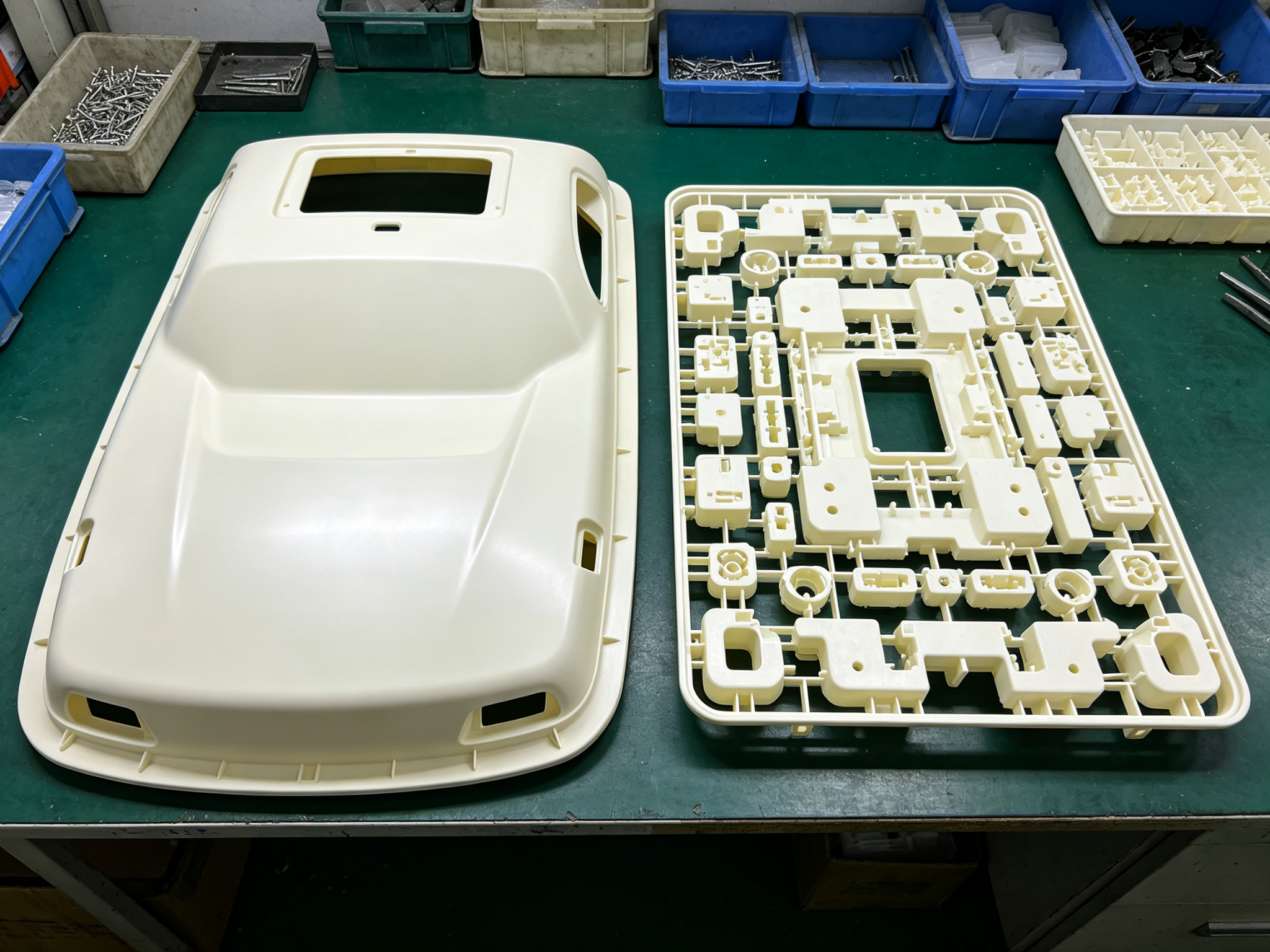
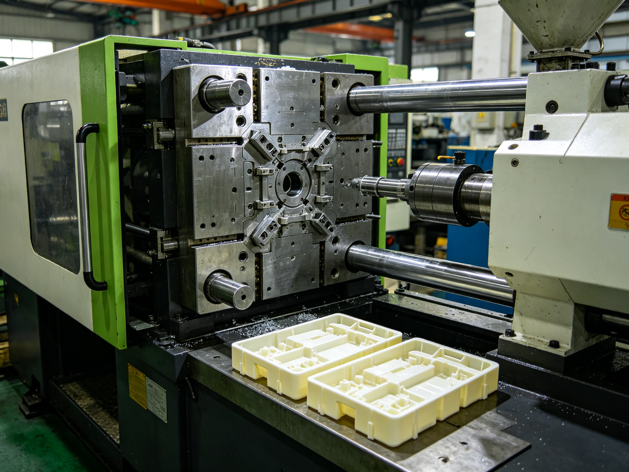
El moldeo por inyección comienza con gránulos de resina. Los gránulos se funden dentro de un cilindro calentado y un husillo inyecta el material fundido a alta presión en un molde metálico cerrado de dos caras, normalmente de aluminio o acero. El molde define ambas caras de la pieza. Una vez que se llena la cavidad, la máquina aplica presión de compactación y mantenimiento, y la pieza se enfría antes de su expulsión. Los moldes multicavidad producen varias piezas por ciclo, y es precisamente ahí donde el proceso gana en velocidad cuando se trata de la producción en serie.
La diferencia práctica no radica simplemente en “lámina frente a gránulo”. Más bien, se reduce a qué superficies controla el molde y a si este puede crear detalles en ambas caras. El termoformado convencional de una sola lámina controla una cara; el moldeo por inyección controla ambas.
Las cuatro preguntas que definen el proceso
La mayoría de las comparaciones entre estos dos procesos se reducen a cuatro preguntas. Analízalas por orden, ya que cualquiera de ellas por sí sola puede zanjar el debate.
1. Dimensiones y geometría de la pieza
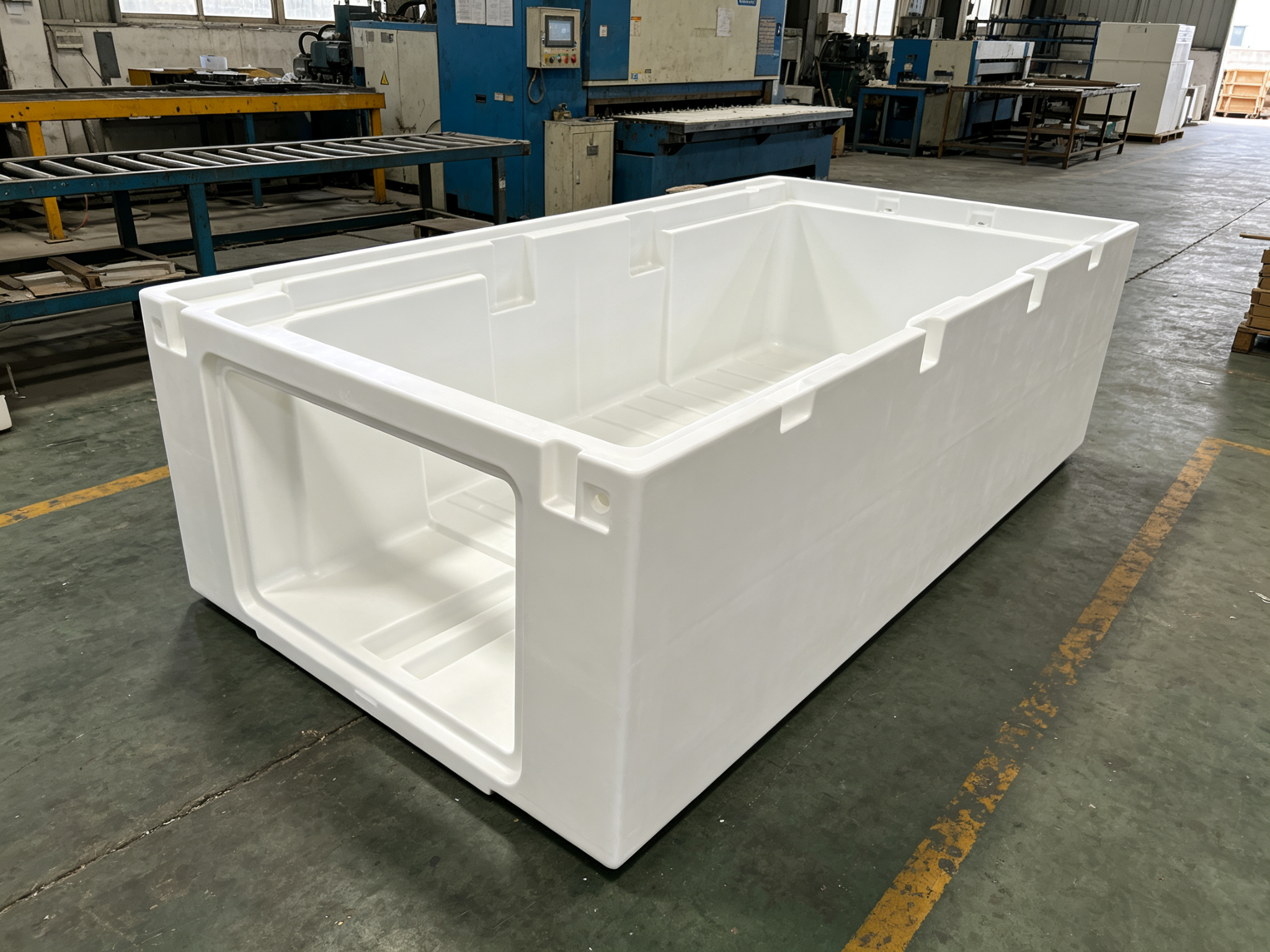
El termoformado destaca en la fabricación de piezas grandes, de paredes delgadas y de cara abierta, de hasta varios metros de diámetro —como carcasas, tapas, paneles y bandejas—. Los revestimientos de frigoríficos, los paneles interiores de vehículos y las bañeras se fabrican mediante termoformado porque el molde de inyección equivalente requeriría una enorme capacidad de herramientas y de prensa.
Por el contrario, las dimensiones del molde, el volumen de inyección, el área proyectada y la fuerza de sujeción disponible limitan el moldeo por inyección. Las máquinas de gran formato pueden moldear piezas de más de medio metro, pero el tamaño de la máquina y el coste del utillaje aumentan rápidamente a medida que crece el área proyectada. Por lo tanto, la pieza concreta y el equipo disponible marcan el límite práctico.
También hay que tener en cuenta un límite de profundidad. El termoformado adelgaza la lámina a medida que se estira, por lo que los embutidos extremos pueden producir esquinas delgadas y débiles. Los ingenieros pueden evaluar la intensidad del embutido utilizando las relaciones de embutido H:D, areales o lineales, dependiendo de la geometría de la pieza.
2. Volumen anual
El termoformado resulta más rentable en volúmenes bajos y medios, ya que el coste de adquisición de los moldes es bajo y su cambio es rápido. El moldeo por inyección resulta más rentable en volúmenes elevados, ya que el coste por pieza se reduce a medida que el molde se amortiza a lo largo de una tirada de producción prolongada.
La línea divisoria entre ambos procesos no es una cifra fija. Por el contrario, varía en función del tamaño y la complejidad de la pieza, un aspecto que se explica con detalle en el apartado sobre costes que figura a continuación. La conclusión útil en esta fase es orientativa: si tu previsión va en aumento, la rentabilidad está cambiando a tu favor, incluso si el volumen actual sigue favoreciendo al termoformado.
3. Tolerancias y espesor de la pared
El moldeo por inyección suele ofrecer un mayor control dimensional y una mayor repetibilidad. El molde define las secciones nominales de las paredes, y un buen diseño de moldeo por inyección utiliza un espesor de pared uniforme con transiciones graduales para controlar la contracción, las marcas de hundimiento y la deformación.
El termoformado estira la lámina, por lo que las paredes se adelgazan allí donde el material se estira: en las esquinas, en las cavidades profundas y en las paredes laterales empinadas. El espesor varía a lo largo de la pieza y las tolerancias suelen ser más holgadas. Por consiguiente, si el diseño requiere propiedades estructurales uniformes o elementos de acoplamiento estrictamente controlados, el moldeo por inyección suele ser la opción más adecuada.
4. Acabado superficial y características integradas
El moldeo por inyección reproduce superficies muy detalladas y permite integrar roscas, encajes a presión, bisagras vivas y socavados mediante elementos como correderas y elevadores. Ambas caras de contacto con el molde pueden presentar una geometría y una textura controladas.
El termoformado transfiere el máximo nivel de detalle al lado del molde. No hay una segunda superficie de cavidad que dé forma al lado libre, y las roscas o los elementos complejos de doble cara suelen requerir operaciones secundarias. Los socavados y algunos elementos de fijación son posibles con utillaje especializado, pero el moldeo por inyección suele ser superior cuando se requieren detalles funcionales densos en ambas caras.
Factor
Termoformado
Moldeo por inyección
Tamaño de la pieza
Grande, de paredes finas y con la parte frontal abierta
De pequeño a muy grande, dentro de los límites de la máquina
Volumen óptimo
Bajo a medio
De medio a alto
Grosor de la pared
Variable, se va adelgazando en las curvas
Con forma definida por el molde; se prefieren las paredes uniformes
Tolerancia
En general, más holgado
En general, mayor precisión; se puede alcanzar una tolerancia de ±0,05 mm en determinadas características
Detalles y características
Principalmente en el lado del molde; posibilidad de incorporar características especializadas
Ambas caras, encajes a presión, roscas, bisagras
Herramientas
Normalmente, de aluminio o material compuesto de una sola cara
Molde metálico a juego, de aluminio o acero
A dónde va el dinero: el coste de los utillajes frente al coste por pieza
Los dos procesos reparten los costes de forma diferente, y ese reparto es precisamente lo que determina el punto de cruce.
Utillaje (único). Un troquel de termoformado suele ser considerablemente más barato que un molde de inyección de producción comparable, ya que es más sencillo y, por lo general, es de una sola cara. Los troqueles de inyección pueden fabricarse en aluminio o acero, por lo que la diferencia de coste no es una relación fija de 10 a 1.
Coste por unidad (recurrente). El moldeo por inyección suele resultar más económico por pieza cuando se producen grandes volúmenes. Los moldes multicavidad y la automatización aumentan la producción, y no hay que recortar el perímetro. El termoformado, por el contrario, conlleva un coste adicional por la lámina que sobresale de la pieza acabada y suele requerir un paso de recorte independiente.
El coste del termoformado, por tanto, depende principalmente del precio de la lámina, los residuos de recorte y el tiempo de ciclo, factores que varían en función del tamaño de la pieza y del material. En el caso del moldeo por inyección, en cambio, el factor que determina el coste es en qué medida se amortiza el molde a lo largo de la tirada.
Si se combinan estas dos categorías de costes, se obtiene un punto de cruce. A bajos volúmenes, predomina el bajo coste del utillaje y gana el termoformado. Cuando los volúmenes son elevados, prevalece el bajo coste por pieza y gana el moldeo por inyección. El punto en el que se cruzan las líneas depende del tamaño y la complejidad de la pieza. Las piezas más grandes y complejas se mantienen en el termoformado incluso en los niveles más altos de la curva de volumen, ya que sus moldes de inyección resultan desproporcionadamente caros.
Plazo de fabricación de las herramientas y flexibilidad de diseño
El plazo de fabricación de los utillajes es la primera distinción práctica entre los procesos, y tanto los cambios de diseño como la vida útil del molde apuntan en la misma dirección.
Termoformado
Moldeo por inyección
Primer artículo
Semanas; días para las herramientas prototipo
De semanas a meses
Cambio de diseño
Un reacondicionamiento más económico y rápido
Más caro, sobre todo en lo que respecta a las herramientas de producción
Vida útil del molde
Suelen ser más cortos y más fáciles de volver a mecanizar
Normalmente es más largo cuando se utilizan herramientas de acero de producción
Los talleres pueden volver a mecanizar un molde de termoformado de aluminio de forma rápida y económica, por lo que una pieza puede seguir evolucionando durante la producción piloto sin salirse del presupuesto. Los moldes de inyección para producción —especialmente los de acero— suelen ser más caros y su reelaboración lleva más tiempo. En el caso de los moldes complejos, a veces resulta más práctico fresar una nueva cavidad que modificar en profundidad una ya existente.
Por eso, el momento en que se toma la decisión es tan importante como la decisión en sí misma. El proceso que elijas ahora es también una apuesta sobre hasta qué punto seguirá evolucionando el diseño.
Las señales que indican que es hora de cambiar
Hay cuatro indicios que señalan cuándo el moldeo por inyección es la mejor opción:
Congelación del diseño. Las modificaciones económicas dejan de ser rentables una vez que la geometría queda fijada. La ventaja de que “es barato modificarlo” desaparece, y la desventaja de que “es caro cambiarlo” ya no tiene importancia. Esta suele ser la primera señal a la que hay que prestar atención.
El volumen se acerca a la zona de cruce. Cuando la previsión anual va por buen camino para superar el umbral de rentabilidad, el ahorro por pieza empieza a compensar la inversión en utillaje. Merece la pena hacer un modelo en lugar de basarse en conjeturas: realiza la comparación entre el coste del utillaje y el ahorro por pieza para tu pieza concreta.
Las tolerancias y los requisitos de uniformidad son cada vez más exigentes. Cuando los objetivos de capacidad dimensional o repetibilidad empiezan a superar lo que el termoformado puede garantizar de forma fiable, el moldeo por inyección se convierte en una opción más atractiva. Cabe señalar que los requisitos del PPAP y de Cp/Cpk miden o documentan la capacidad del proceso; por sí solos, no determinan el proceso de moldeo.
El debate sobre los costes da un giro. Cuando el coste por pieza se convierte en la partida más importante, en lugar del coste de los utillajes, el programa ha superado el punto en el que el bajo coste de los utillajes del termoformado resulta beneficioso. Presta atención a en qué aspectos se centra la mayor parte del debate sobre costes de tu equipo.
Muchos programas llevan a cabo ambos procesos a lo largo de su ciclo de vida. Una estrategia habitual es recurrir al termoformado durante los primeros años —mientras el diseño aún está en fase de evolución y el volumen de producción es bajo— y, posteriormente, pasar al moldeo por inyección una vez que el diseño se ha consolidado y el volumen supera el umbral mínimo. De este modo, se mantiene bajo el gasto en utillaje durante la fase de mayor riesgo y, posteriormente, se aprovechan los ahorros por pieza que ofrece el moldeo por inyección.
Si el diseño aún no se ha fijado, el primer paso más económico suele ser un prototipo funcional —mediante mecanizado CNC o impresión 3D— para definir la geometría y el ajuste antes de fabricar ningún molde.
Cuando se opta por el moldeo por inyección, PartsMastery se encarga de todo el proceso relacionado con el plástico de principio a fin: desde los moldes de prototipo hasta los de producción, incluyendo el moldeo con insertos y el sobremoldeo. El moldeo por inyección mantiene tolerancias de alrededor de ±0,05 mm, y los plazos de entrega de los moldes de producción comienzan en unos 15 días.
Conclusión
Elige el proceso respondiendo a cuatro preguntas: tamaño de la pieza, volumen anual, requisitos de tolerancia y necesidades de características. A continuación, determine el momento adecuado para el cambio prestando atención a cuatro indicadores: congelación del diseño, aumento del volumen de producción, endurecimiento de los requisitos de tolerancia y un cambio en la negociación de los costes. El termoformado suele ser más ventajoso en cuanto al coste del utillaje y la rapidez para obtener la primera pieza; el moldeo por inyección suele ser más ventajoso en cuanto al coste por pieza y al control dimensional en la producción en serie.
Si tu volumen apunta al moldeo por inyección, sube tu pieza para obtener una revisión gratuita de DFM y un presupuesto al instante. La revisión abarca la fabricabilidad y el enfoque del molde, y te indicará con claridad si el termoformado sigue siendo la mejor opción para tu volumen actual.
Preguntas frecuentes
¿A partir de qué volumen debería pasar del termoformado al moldeo por inyección?
No hay una cifra concreta. El punto de equilibrio varía en función del tamaño y la complejidad de la pieza: las piezas más grandes se adaptan mejor al termoformado a medida que aumenta el volumen de producción. Realiza la comparación entre el coste del utillaje y el coste por pieza para tu pieza concreta, o solicita presupuestos para ambas opciones.
¿Se puede utilizar el termoformado para la creación de prototipos antes del moldeo por inyección?
Por supuesto. El bajo coste de las matrices de termoformado lo convierte en una opción habitual para validar la forma y el aspecto en lotes pequeños. El mecanizado CNC y la impresión 3D también son buenas opciones para crear prototipos funcionales antes de fabricar un molde.
¿Se utilizan materiales diferentes en el termoformado y en el moldeo por inyección?
Ambos procesos utilizan termoplásticos, pero la forma de la materia prima difiere. El termoformado parte de láminas extruidas; los materiales más habituales son el ABS, el PETG, el HIPS, el PVC y el PP. El moldeo por inyección parte de gránulos y abarca una gama más amplia, incluyendo resinas reforzadas con fibra de vidrio y resinas técnicas que no se prestan bien al conformado en láminas.
¿Qué debo comprobar antes de pasar una pieza de plástico a la fase de producción?
Confirma los objetivos de tolerancia y repetibilidad, la elección del material y la clasificación de la vida útil del molde. Para los programas del sector de la automoción o el sector médico, comprueba las certificaciones: las normas ISO 9001, IATF 16949 e ISO 13485 cubren los casos más habituales.