


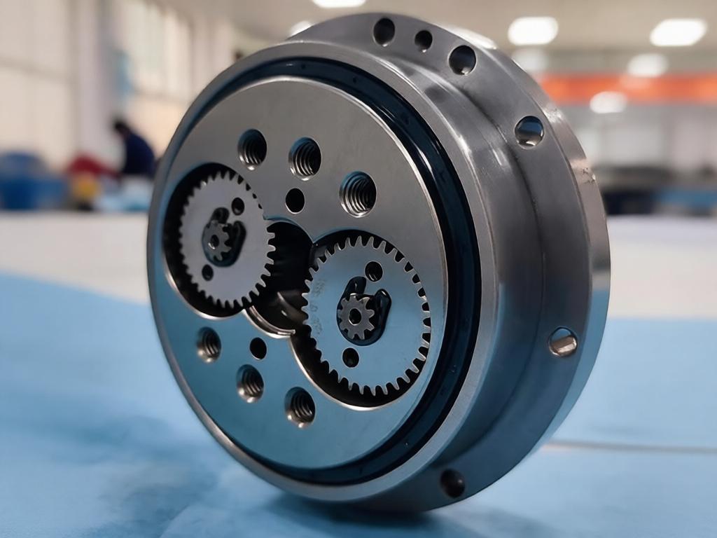
As the core transmission unit in robotic joints, robot reducers perform three critical functions: reducing input speed, amplifying output torque, and enabling precise motion control. They contain dozens of precision mechanical parts, including reducer housings, input and output shafts, connection flanges, bearing seats, eccentric components, and bushings. During continuous cyclic robot operation, these components sustain repeated alternating loads and impact forces.
Dimensional accuracy, concentricity, runout, surface roughness, and fit tolerances directly determine joint stability, repeat positioning accuracy, and overall service life. For this reason, CNC precision machining has become the standard manufacturing method for robot reducer components, thanks to its high accuracy, consistent repeatability, and customizability.
PartsMastery specializes in precision component manufacturing for robotic transmission systems. With in-house capabilities including CNC turning, milling, boring, and multi-axis simultaneous machining, we deliver full-cycle custom manufacturing services — from prototype development and low-volume trials to full-scale mass production — tailored to the structural and accuracy requirements of all reducer types.
1. Core Machining Challenges for Robot Reducer Components
1.1 Strict Concentricity and Geometric Tolerance Requirements
Inside a reducer, shafts and bearings, housings and bearing seats, and output flanges and shafts all require precise concentric alignment. Even minor concentricity deviation causes transmission vibration, operational noise, and uneven load wear, which significantly shorten reducer service life over time. For this reason, geometric tolerances between bearing bores, mating diameters, and positioning datums remain the top quality priority throughout production.
1.2 High Surface Quality Requirements for Precision Mating Faces
Beyond dimensional accuracy, features such as bearing mating surfaces, seal grooves, mounting datum planes, and gear engagement faces carry strict requirements for surface roughness, flatness, and roundness. Inadequate surface quality leads to seal failure, lubricant leakage, and bearing creep, all of which directly degrade transmission performance and reliability.
1.3 Deformation Control for Thin-Wall and Complex Geometries
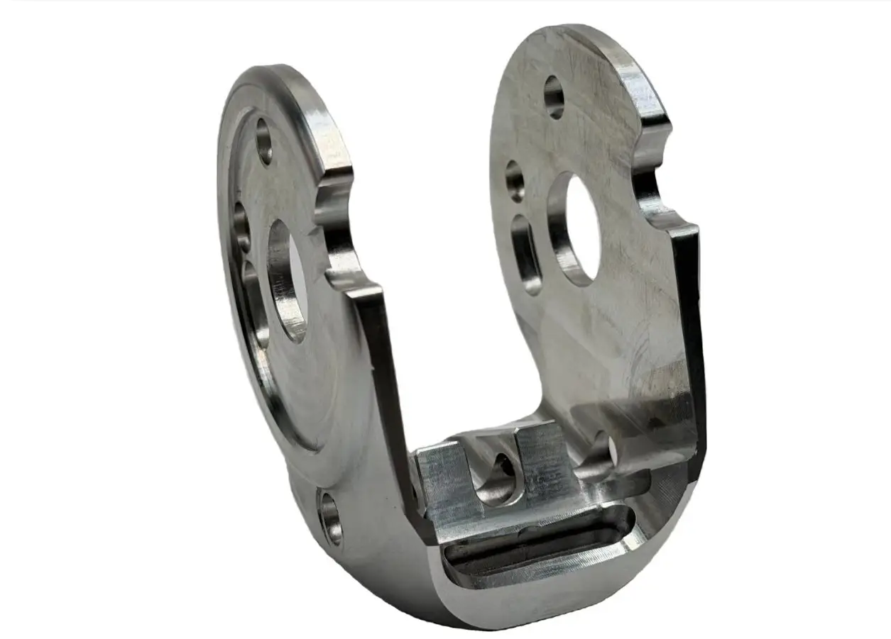
Reducer housings are typically thin-walled hollow structures, making them susceptible to elastic deformation from clamping and cutting forces. Eccentric discs, multi-hole flanges, and irregular connection brackets also feature complex geometries. Traditional machining requires multiple setups, which introduce cumulative positioning error. Controlling deformation and maintaining positional consistency across features is the central manufacturing challenge.
2. Process Matching for Common Reducer Components
Different reducer components require matched machining processes and quality control priorities to achieve the optimal balance of accuracy, efficiency, and production cost.
| Component Type | Primary Machining Process | Key Quality Control Points |
|---|---|---|
| Input / Output Shafts | CNC Turning, Precision Grinding | Outer diameter tolerance, concentricity, runout, surface roughness |
| Reducer Housing | CNC Milling, Precision Boring | Bearing bore concentricity, mounting surface flatness, hole position accuracy |
| Connection Flange | Combined Turning & Milling | Spigot concentricity, mounting hole position, end face flatness |
| Eccentric Parts / Cam Discs | 4-Axis / 5-Axis Simultaneous Machining | Eccentricity accuracy, profile accuracy, phase position |
| Bearing Seats / Bushings | CNC Turning, Precision Internal Boring | Inner/outer diameter concentricity, fit tolerance, roundness |
3. Full-Process Standardized Manufacturing Control System
Reducer component precision does not depend on a single operation. It relies on standardized quality control across the entire production flow. At PartsMastery, we have established a complete quality chain from drawing intake to finished product delivery.
3.1 Upfront DFM Manufacturability Review
Before production begins, we conduct a full DFM (Design for Manufacturing) analysis based on customer 3D models and 2D engineering drawings. The review identifies potential risks such as thin-wall deformation zones, excessively tight tolerances, and impractical hole placements. We then provide early structural optimization recommendations to reduce downstream manufacturing costs and rework rates at the design stage.
3.2 Process Planning and Unified Datum Strategy
We develop a custom process route for each part geometry, with carefully allocated roughing, semi-finishing, and finishing stock allowances. Critical features are completed in the same setup wherever possible to eliminate cumulative error from datum shifts. For thin-walled parts, we design dedicated fixturing with optimized clamping points and forces to control machining deformation.
3.3 In-Process Inspection Between Operations
We perform dimensional verification at key process nodes — including datum surface finishing, bearing bore fine boring, and critical feature forming. This proactive approach catches deviations early and prevents error accumulation through to final operations, significantly reducing scrap costs and material waste.
3.4 Final Inspection and Surface Finishing
Finished parts undergo full-dimensional verification of concentricity, positional accuracy, and flatness using a Coordinate Measuring Machine (CMM). We also offer secondary operations including deburring, anodizing, heat treatment, and electroplating to meet wear, corrosion, and appearance requirements.
We select the optimal engineering material based on each reducer’s load rating, operating speed, working environment, and lightweight requirements.
| Material Grade | Core Performance Characteristics | Typical Component Applications |
|---|---|---|
| 6061-T6 Aluminum Alloy | Lightweight, good machinability, excellent corrosion resistance | Reducer housings, connection flanges, end covers |
| 7075-T6 Aluminum Alloy | High strength, excellent strength-to-weight ratio | High-load flanges, structural support components |
| 40Cr Alloy Steel | High strength, heat treatable, good wear resistance | Input/output shafts, drive pins, eccentric components |
| 45 Carbon Steel | Stable mechanical properties, good machinability | Standard flanges, bearing seats, bushing bases |
| 304 / 316 Stainless Steel | Corrosion resistant, stable mechanical performance | Special-environment housings, shafts, seal components |
| Copper Alloy | Wear resistant, good thermal conductivity, self-lubricating | Bushings, guide sleeves, wear mating components |
5. Key Control Measures for Improved Machining Accuracy
To meet the high precision requirements of reducer components, we apply targeted control measures to stabilize manufacturing quality:
- Unified datum principle: Critical outer diameters, end faces, and bearing bores share a single machining datum to minimize datum shift error
- Layered cutting process: Roughing, semi-finishing, and finishing are performed in sequence to release internal material stress evenly
- Precision boring process: Bearing bores are machined in rough – semi-finish – finish boring stages to ensure bore accuracy and concentricity
- Tool life management: Tool wear compensation and replacement schedules are set by part count to ensure batch-to-batch dimensional consistency
- Environmental temperature control: Precision machining areas maintain stable ambient temperature to reduce thermal deformation effects on dimensional accuracy
6. PartsMastery Custom Manufacturing Service Support
PartsMastery supports reducer component manufacturing for all robot types, including industrial robots, collaborative robots, SCARA robots, palletizing robots, and welding robots.
During prototype development, we deliver small quantities quickly to support assembly validation and performance testing. During full production, we use standardized processes and SPC statistical process control to ensure consistent batch-to-batch dimensional accuracy and interchangeability. With integrated material selection, process optimization, surface finishing, and protective packaging, we help robotics customers shorten development cycles and reduce overall manufacturing costs.
Conclusion
The performance of a robot reducer is built on the manufacturing precision of every individual component. Only systematic control over materials, processes, datums, and inspection can consistently deliver high-quality parts that meet demanding transmission requirements.
With proven CNC precision machining capabilities and deep expertise in transmission component manufacturing, PartsMastery delivers reliable custom machining solutions for robot reducer components, supporting the development and production of high-precision robotic transmission systems.