






As automotive lightweighting accelerates — driven especially by strict range and efficiency rules for electric vehicles — manufacturers increasingly adopt aluminum thin-walled housings, mounting brackets, heat sinks and electronic connectors. By design, thin-wall structures deliver structural rigidity within limited installation space while reducing material usage and overall vehicle weight. Even so, reduced wall thickness also significantly increases manufacturing complexity.
To address this industry-wide challenge head-on, PartsMastery has developed a dedicated precision machining system for automotive thin-walled parts. It controls deformation at every stage, from upfront design review to final inspection, and as a result, it ensures consistent dimensional accuracy across every production batch.
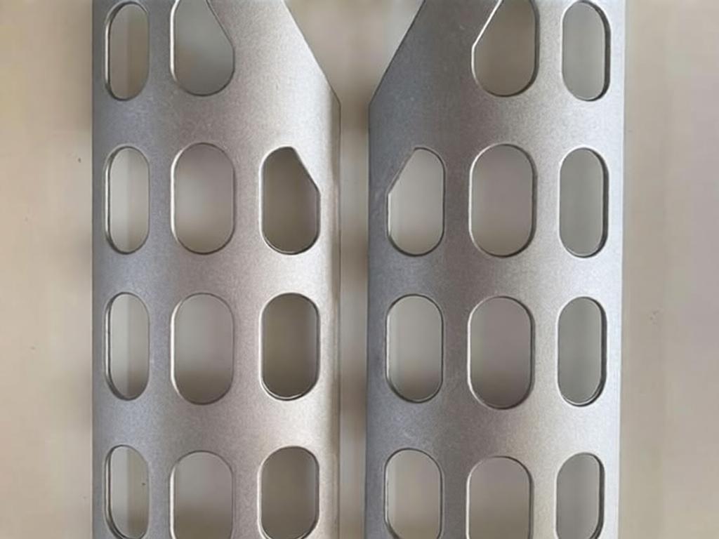
Three Core Machining Challenges for Automotive Thin-Walled Parts
1. Deformation Springback from Clamping and Cutting Forces
By their very nature, thin-walled parts have low structural rigidity. Excessive clamping force causes local plastic deformation of thin walls. For instance, dimensions may read within tolerance while the part sits in the fixture, but internal stress releases once you unclamp it, which leads to dimensional springback and out-of-tolerance results. Along the same lines, excessive cutting force also causes wall deflection and uneven wall thickness.
2. Cutting Vibration Degrading Accuracy and Surface Quality
In practical manufacturing terms, thin-wall sections have low damping characteristics, making them prone to chatter during tool passes. In most cases, this manifests as surface waviness, increased roughness and heavy edge burrs. In more extreme scenarios, it causes hole position shift and poor flatness of sealing surfaces, directly compromising assembly precision and sealing performance. Most notably, long unsupported walls and deep cavity sidewalls carry the highest vibration risk.
3. Internal Stress Deformation from Improper Material Removal Sequence
We typically machine thin-walled parts from solid billets, and the process removes a very high percentage of the starting material. If you finish thin-wall sections to final dimensions too early, subsequent material removal breaks the internal stress balance and triggers global structural deformation. For this very reason, poorly planned machining sequences and improper stock allocation rank among the leading causes of post-machining dimensional deviation.
Systematic CNC Precision Machining Solution
To tackle these pain points at their source, PartsMastery delivers a complete closed-loop solution built on extensive automotive thin-wall machining experience. It directly targets the root causes of thin-wall machining defects for predictable, repeatable results.
1. Upfront DFM Manufacturability Assessment
To kick off every project, we perform an upfront DFM manufacturability assessment. Every machining solution starts with a thorough review of your product data. Specifically, our engineers analyze wall thickness, wall height, cavity depth, hole pattern distribution, mounting surface tolerances and other critical metrics to identify high-risk machining areas.
Where the design permits flexibility, we provide optimization recommendations without impacting function or assembly fit. Common examples include adding local reinforcing ribs, integrating dedicated clamping lugs, or adjusting draft angles in deep narrow cavities. Over the long term, such changes improve machining stability at the source and reduce deformation risk in later mass production.
2. Material-Specific Process Selection
Moving on to process selection, we match each material to a tailored manufacturing strategy. Automotive thin-walled parts cover aluminum alloys, stainless steel, engineering plastics and more. Each material behaves very differently during cutting, so we tailor all process parameters accordingly.
| Material Type | Typical Automotive Applications | Key Machining Control Points |
|---|---|---|
| Aluminum Alloy (6061 / 7075, etc.) | Housings, brackets, heat sinks, in-vehicle connectors | Control cutting heat buildup, minimize thin-wall deflection and built-up edge |
| Stainless Steel (304 / 316, etc.) | High-strength connectors, sealing components | Reduce cutting load, control work hardening and tool wear |
| POM Engineering Plastic | Lightweight insulating structures, interior functional parts | Control cutting force and temperature to avoid stress-induced dimensional shift |
| PEEK High-Performance Plastic | High-end functional components, wear-resistant parts | Strict temperature control to ensure post-machining dimensional stability |
For parts with multi-axis curved surfaces, deep cavities or features inaccessible from a single direction, we deploy 4-axis and 5-axis machining. This approach cuts re-fixturing errors and clamping deformation, and it also completes all features in a single setup for higher accuracy.
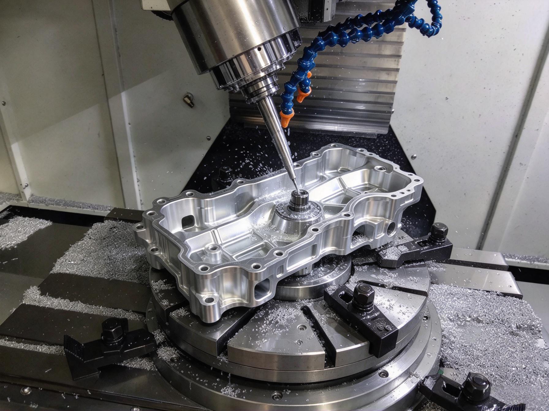
3. Step-by-Step Machining Strategy
Next in the process framework comes our structured step-by-step machining strategy, applied to every thin-wall part. Put simply, we use a three-stage machining approach: structure stabilization → gradual material removal → final feature finishing.
- Roughing stage: To begin with, we use high-feed removal of bulk stock with generous allowance left on thin-wall sections. We prioritize overall structural rigidity to avoid premature weakening of the part.
- Semi-finishing stage: Progressing to the next phase, we gradually refine part contours, release internal stress and stabilize part geometry, leaving uniform stock for finishing.
- Finishing stage: To wrap up the machining sequence, we use light-cut parameters to finalize thin walls, mounting surfaces and precision holes, ensuring dimensional accuracy and surface quality.
All things considered, this strategy effectively prevents material deformation from excessive single cuts, maintains structural stability throughout the process and protects critical feature accuracy.
4. Flexible Workholding for Deformation Suppression
Beyond cutting strategy alone, we also use flexible workholding to suppress deformation. We design custom workholding solutions around each part’s geometry to minimize clamping deformation:
- Clamping points sit first on rigid solid sections of the part, so we never apply direct pressure on thin walls.
- For large thin-wall panels and deep cavity structures, we add auxiliary supports, vacuum chucks and soft jaws to distribute clamping force and reduce local deflection.
- For high-volume production runs, we iterate fixture design based on first article results to ensure consistent clamping conditions across batches.
5. Optimized Tool Paths and Cutting Parameters
On top of workholding improvements, we optimize tool paths and cutting parameters for even greater control. We reduce cutting force and vibration through refined tool path engineering and targeted parameter control:
- For thin-wall sections specifically, we use light depth of cut and high feed rates to reduce radial tool pressure on the wall.
- Furthermore, we implement smooth climb milling paths and gradual direction changes to avoid vibration from abrupt cutting direction shifts.
- For deep cavity operations in particular, we strictly limit tool overhang and use rigid tooling to minimize deflection-related dimensional errors.
6. Full-Dimensional Quality Inspection System
Last but not least, we back every process with a full-dimensional quality inspection system. Our multi-stage quality control system ensures every part meets automotive industry precision requirements:
- First article validation: Our inspectors perform a full dimensional inspection of the first part to confirm process stability before batch production begins.
- In-process inspection: They also spot-check critical dimensions and wall thickness during machining to correct for tool wear and parameter drift.
- Final inspection: Before shipment, we verify hole diameters, position tolerances, flatness, perpendicularity and wall thickness against all drawing requirements. For high-precision parts, we use a Coordinate Measuring Machine (CMM) to validate geometric tolerances.
- Visual inspection: As a final quality check, we inspect 100% of parts for surface finish, burrs and handling damage prior to shipment.
Full-Lifecycle Production Services
Looking beyond core machining capabilities, PartsMastery supports every stage of your project from prototype validation to full-scale mass production, matched to your project phase and production goals.
1. Single Prototyping: Manufacturability Verification
Starting with single prototyping, the focus rests on manufacturability verification. Before you launch full production, we produce CNC machined prototypes to validate dimensional fit, structural integrity and functional performance. If prototype machining reveals deformation risks or accessibility issues, we also provide concurrent design optimization recommendations to resolve problems early and avoid costly rework later.
2. Low-Volume Pilot Production: Consistency Control
Moving into low-volume pilot production, priorities shift to consistency control. As projects move into pilot runs, the focus naturally shifts from making one good part to consistently producing repeatable parts. We standardize all workholding methods, machining programs, tooling parameters and inspection standards to ensure consistent, replicable quality across the pilot batch.
3. High-Volume Production: Efficiency & Cost Optimization
Scaling up to high-volume production, we balance efficiency and cost optimization. In full-scale production, targeted process refinements improve machining efficiency, extend tool life and balance inspection frequency to deliver both precision and cost effectiveness. Our standardized production system maintains reliable lead times and consistent batch quality to meet OEM tiered supply requirements.
Frequently Asked Questions
Below, we answer the most frequently asked questions about automotive thin-wall machining.
Q1: What is the minimum machinable wall thickness for automotive thin-walled parts?
To start with, there is no universal minimum wall thickness. Achievable wall thickness depends on material properties, wall height, span, support structure, machining direction, tooling capability and tolerance requirements. Industry convention often defines walls under 2mm as thin-walled, but this serves only as a rough reference point. For a definitive answer, you always need a full manufacturability assessment based on your specific 3D model.
Q2: Why do thin-walled parts deform after machining?
Put simply, the most common root causes include internal stress release, cutting force deflection, clamping-induced deformation, machining heat effects and improper material removal sequence. Parts often measure correctly while clamped in the fixture, but springback after unclamping causes dimensional shift — and this is a defining characteristic of thin-wall machining.
Q3: Can I get a machining quote directly from 3D drawings?
Absolutely. PartsMastery accepts all major 3D CAD formats including STP and STEP. As soon as we receive your data, we perform a full DFM assessment and provide a detailed quote based on material, quantity, tolerance requirements and surface finish specifications.
Q4: Do you support low-volume automotive component orders?
Yes, fully. We offer a full range of production scales: single prototypes, low-volume pilot runs and high-volume mass production. To match your needs, we select the optimal production method based on your part geometry, lead time and precision requirements.
Conclusion
All things considered, quality in automotive thin-wall machining depends on precise control of deformation, vibration and internal stress — not just raw machine capability. To achieve consistent results, you need a well-designed process chain, workholding strategy and inspection system to consistently deliver parts that meet automotive industry standards.
PartsMastery specializes in precision custom components for the automotive sector, with proven expertise in thin-wall machining and deformation control. We work with aluminum, stainless steel, engineering plastics and more, delivering one-stop service from DFM optimization and prototype validation through to full production. To get started, submit your 3D models and technical requirements, and our engineering team will develop a fully tailored machining solution and quotation for your project.