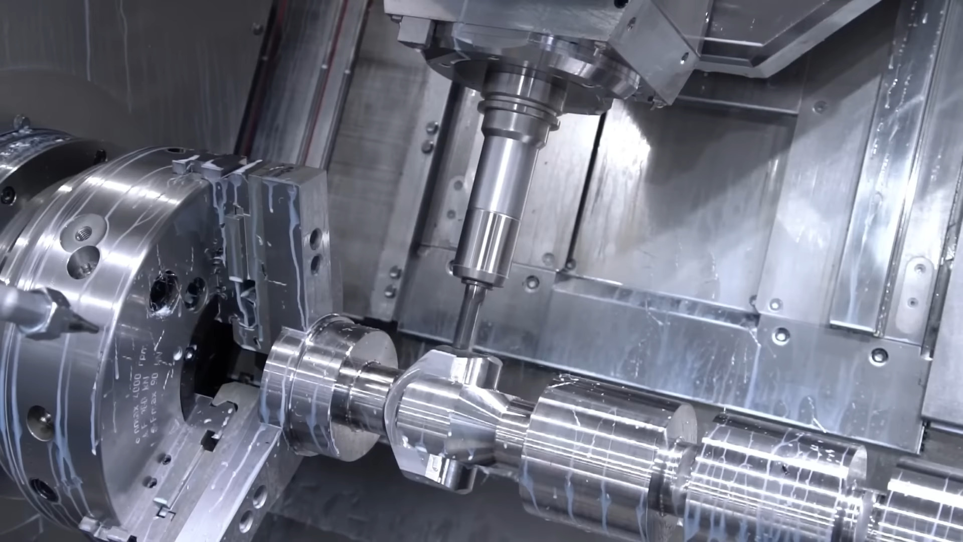
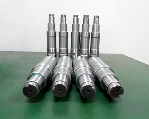
Les arbres sont des composants essentiels qui transmettent le couple et soutiennent les pièces rotatives dans les systèmes mécaniques. Un arbre peut ressembler à un simple cylindre, mais ses performances dépendent souvent de la relation coordonnée entre son diamètre, ses épaulements, ses filetages, ses rainures de clavette, son faux-rond, sa rectitude et son état de surface. Le tournage CNC permet généralement d’obtenir la géométrie principale de l’arbre. Les opérations de fraisage, de perçage, de rectification et de finition viennent ensuite compléter les caractéristiques fonctionnelles et les zones nécessitant une haute précision.
Cet article aborde de manière systématique les principes techniques de l’usinage des arbres, les principaux procédés CNC, les types d’arbres et matériaux courants, le contrôle des tolérances, le traitement thermique et la finition de surface, les défis liés aux arbres longs, le contrôle qualité, les domaines d’application et l’analyse des coûts. Il offre aux ingénieurs une référence pratique pour l’ensemble du processus, de la conception à la production.
1. L’essence et la valeur fondamentale de l’usinage des arbres
L'usinage d'arbres consiste à transformer des barres, des pièces forgées ou d'autres ébauches en pièces mécaniques cylindriques présentant une géométrie et des caractéristiques fonctionnelles contrôlées. La géométrie des arbres étant principalement rotative, le tournage CNC s'impose naturellement comme le procédé d'usinage principal. Lorsque les conceptions nécessitent des rainures de clavette, des méplats, des alésages, des filetages ou des cotes finales plus strictes, les fabricants ont recours au fraisage, au perçage, à la rectification et à d’autres méthodes complémentaires.
Un arbre fini n’est jamais une simple pièce ronde. Toutes ses dimensions et caractéristiques doivent fonctionner de concert autour d’un axe de rotation commun. Ce n’est qu’ainsi que les roulements, les engrenages, les joints d’étanchéité, les accouplements et autres composants peuvent fonctionner comme prévu. La cohérence de l’axe est l’exigence la plus importante qui distingue les arbres des autres pièces mécaniques.
1.1 Fonctions et charges des arbres mécaniques
La fonction principale d'un arbre mécanique est de transmettre le mouvement de rotation et le couple d'un composant à un autre. Les arbres de moteur, de transmission, de pompe et de boîte de vitesses remplissent tous cette fonction de différentes manières. Les arbres supportent également des engrenages, des roulements, des poulies, des roues, des rouleaux et d’autres pièces rotatives tout en subissant des charges de flexion et des charges cycliques.
La combinaison de la rotation et de la charge rend la géométrie de l’arbre cruciale. Le diamètre influe non seulement sur la taille globale, mais aussi sur la rigidité, l’ajustement des roulements, la capacité de couple et la réponse à la flexion. Les épaulements assurent le positionnement axial des composants. Les rainures de clavette, les cannelures ou d’autres structures transmettent le couple entre l’arbre et les pièces reliées.
À mesure que la vitesse et la charge augmentent, même les plus infimes erreurs géométriques s’amplifient. Un désalignement qui semble négligeable au repos peut provoquer des vibrations, une usure inégale ou un bruit anormal dès que l’arbre tourne à grande vitesse.
1.2 Pourquoi la précision est-elle importante dans l'usinage des arbres ?
Même lorsque le diamètre d’un arbre correspond parfaitement à sa valeur nominale, celui-ci peut tout de même présenter une défaillance en service. Le faux-rond, la concentricité, la rectitude et l’état de surface sont tout aussi importants que les dimensions de base. Ces facteurs déterminent ensemble la manière dont l’arbre tourne et la façon dont les pièces d’accouplement entrent en contact avec sa surface.
Un logement de roulement trop grand entraîne un serrage insuffisant et des contraintes d'assemblage anormales. Un logement trop petit peut permettre un mouvement relatif entre l'arbre et le roulement. Des problèmes similaires surviennent lorsque les logements de roulements situés sur des diamètres d'épaulement différents ne sont pas alignés autour d'un axe commun.
L’état de surface au niveau des emplacements des roulements et des joints est tout aussi critique. Une surface rugueuse augmente le frottement ou accélère l’usure. Une surface de joint inadéquate endommage les éléments d’étanchéité et réduit la durée de vie. Par conséquent, la précision d’un arbre nécessite une approche globale tenant compte des dimensions, de la géométrie, de l’alignement et de l’état de surface — et non pas une simple valeur de tolérance.
2. Types courants d'arbres usinés
Il existe de nombreuses façons de classer les arbres, mais du point de vue de l'usinage, la géométrie prime sur les appellations. Un simple arbre droit et un arbre cannelé à diamètres multiples peuvent remplir des fonctions de rotation similaires, mais leurs exigences de fabrication diffèrent considérablement. Comprendre leur géométrie principale permet de déterminer les opérations d'usinage nécessaires.
2.1 Arbres lisses et arbres étagés
Un arbre droit présente un diamètre pratiquement constant sur toute sa longueur utile. Il est relativement facile à usiner et convient aux rouleaux, aux tiges de guidage, aux arbres de support et aux systèmes d'entraînement simples.
Un arbre étagé se compose de plusieurs tourillons de diamètres différents, séparés par des épaulements. Ces épaulements offrent aux roulements, engrenages, joints d'étanchéité, entretoises et accouplements des positions de montage bien définies. Les différents tourillons devant partager un axe de rotation commun, les arbres étagés exigent un contrôle plus rigoureux du faux-rond et de l'alignement entre les tourillons.
Le tournage CNC est particulièrement efficace pour les arbres étagés. Les opérateurs peuvent généralement usiner plusieurs diamètres concentriques, des épaulements, des rainures et des finitions d’extrémité en un seul serrage, tout en conservant une référence de rotation constante.
2.2 Arbres à clavette et arbres cannelés
Lorsqu'il est nécessaire de transmettre un couple entre un arbre et un composant monté, on utilise généralement des arbres à clavette ou des arbres cannelés. Une rainure de clavette assure une liaison mécanique relativement simple entre l'arbre et un engrenage, une poulie ou un accouplement. Les cannelures répartissent le couple sur plusieurs dents. On y a recours pour une capacité de couple plus élevée, des montages répétés ou un positionnement angulaire précis.
Ces caractéristiques augmentent la complexité de l’usinage, car leur position doit toujours rester correctement alignée par rapport à l’axe. Elles entraînent également des concentrations locales de contraintes. Par conséquent, les concepteurs doivent prendre en compte à la fois la géométrie de l’arbre et les charges, plutôt que de traiter cette caractéristique comme une rainure isolée.
2.3 Arbres creux, coniques et filetés
Les arbres creux permettent de réduire le poids et offrent un rapport rigidité/poids efficace dans les applications qui ne nécessitent pas de section transversale pleine. La difficulté de leur fabrication dépend de la profondeur du trou, de l'épaisseur de la paroi, de la rectitude, ainsi que de la nécessité ou non d'un alignement précis entre les diamètres intérieur et extérieur.
Les arbres coniques sont utiles lorsqu'un auto-centrage ou un contact à ajustement contrôlé est nécessaire. L'angle de conicité et l'état de surface doivent correspondre précisément au composant d'accouplement, car même de faibles écarts affectent l'alignement ou l'état de contact.
Les fabricants ajoutent généralement des filets aux extrémités ou aux sections intermédiaires des arbres à des fins de fixation axiale, de réglage ou d’assemblage. Ils peuvent réaliser ces filets directement lors du tournage ou les réaliser lors d’une opération de filetage distincte, en fonction des dimensions et des spécifications requises.
3. Déroulement du processus d'usinage des arbres
Tous les arbres ne suivent pas le même processus de fabrication. Un simple arbre non trempé peut passer directement du tournage au contrôle. Un arbre de précision comportant des logements de roulements, nécessitant un traitement thermique et respectant une géométrie stricte peut, quant à lui, nécessiter plusieurs opérations d’ébauche et de finition.
Un processus de fabrication type suit la logique suivante : Préparation du matériau → Usinage grossier → Usinage des éléments caractéristiques → Traitement thermique si nécessaire → Usinage de finition / rectification → Traitement de surface → Contrôle final.
3.1 Matière première et usinage de première ébauche
La fabrication d’arbres commence généralement à partir de barres rondes. Pour les composants de plus grande taille ou soumis à des charges plus élevées, les fabricants peuvent également utiliser des pièces forgées ou d’autres ébauches de forme proche de la forme finale. L’étape initiale d’usinage consiste à éliminer l’excès de matière et à former la forme cylindrique de base. À ce stade, l’objectif n’est généralement pas d’atteindre la précision finale. Les opérateurs laissent suffisamment de matière sur les surfaces critiques pour permettre une finition ultérieure, afin de compenser les déformations dues au traitement thermique ou en vue d’un meulage.
L’état du matériau est également déterminant à ce stade. La rectitude, les contraintes résiduelles, la dureté et la qualité de l’ébauche influent toutes sur le comportement de l’arbre lors de l’enlèvement de matière.
3.2 Tournage CNC et usinage de caractéristiques
Le tournage CNC permet de réaliser la majeure partie de la géométrie rotative de l'arbre, notamment les diamètres extérieurs, les paliers, les épaulements, les rainures, les cones et divers types de filetages. La pièce tourne autour de son axe, et l'outil de coupe contrôle avec précision le diamètre et le profil axial.
Les procédés complémentaires permettent généralement de réaliser les caractéristiques non rotatives. Le fraisage permet de réaliser des rainures de clavette, des méplats, des fentes ou des formes de cannelures spécifiques. Le perçage permet de réaliser des trous axiaux ou transversaux. Les équipements modernes multiaxes et combinés tournage-fraisage peuvent parfois réaliser plusieurs de ces opérations en un seul serrage. Lorsque plusieurs caractéristiques doivent être positionnées avec précision par rapport à l’axe de l’arbre, il devient particulièrement important de réduire les repositionnements inutiles.
3.3 Meulage et contrôle final
Le tournage permet d'obtenir une géométrie précise de l'arbre, mais certains logements de roulements, zones d'étanchéité ou surfaces en rotation à grande vitesse nécessitent un contrôle dimensionnel plus strict ou un état de surface plus lisse que ce que le tournage peut garantir de manière constante.
La rectification cylindrique enlève une petite quantité de matière pour rapprocher les diamètres critiques de leur dimension finale tout en améliorant la circularité et la qualité de surface. Elle permet également de corriger les déformations survenues après le traitement thermique. Après l’usinage, le contrôle permet de vérifier si les dimensions de l’arbre sont conformes aux exigences du plan, et pas seulement si l’aspect est correct. Les opérateurs doivent vérifier le diamètre, le faux-rond, la rectitude, l’alignement entre les diamètres fonctionnels et la rugosité de surface.
4. Principales méthodes d'usinage des arbres
Différents procédés d’usinage permettent de résoudre différents problèmes. Le tournage permet d’obtenir la forme de base par rotation. Le fraisage et le perçage ajoutent des caractéristiques locales. La rectification est généralement utilisée pour les surfaces ou les cotes qui exigent une plus grande précision finale. En règle générale, il est plus efficace d’utiliser la bonne combinaison de procédés que d’essayer de regrouper toutes les opérations en une seule.
4.1 Tournage CNC
Le tournage CNC constitue la base de la plupart des opérations d'usinage d'arbres, car il s'adapte naturellement à la géométrie cylindrique. À mesure que l'arbre tourne, l'outil de coupe réalise efficacement des diamètres, des épaulements, des rainures, des cônes et d'autres éléments concentriques.
L’un des principaux avantages du tournage réside dans sa capacité à garantir la cohérence entre les éléments rotatifs associés au cours d’un même serrage. Cela s’avère particulièrement important pour les arbres étagés, où plusieurs diamètres doivent rester précisément alignés. Le tournage offre également une bonne répétabilité dans la production en série. Une fois le programme, le serrage de la pièce et la stratégie d’outillage définis, les opérateurs peuvent reproduire systématiquement la même géométrie sans avoir à procéder à des ajustements manuels répétés.
4.2 Fraisage et perçage à commande numérique
Le fraisage et le perçage permettent de réaliser des éléments que le tournage ne peut pas produire efficacement. Les rainures de clavette, les méplats, les fentes, les trous transversaux, les éléments de fixation et les profils spécifiques en sont des exemples typiques. Le principal défi technique réside dans les relations de position. Même si une rainure de clavette a les dimensions correctes, une position angulaire ou axiale incorrecte par rapport à d’autres éléments entraîne tout de même des problèmes d’assemblage.
Pour les arbres comportant plusieurs éléments tournés et fraisés, réduire au minimum les réglages inutiles et maintenir des repères fiables permet de préserver l'alignement tout au long du processus de fabrication.
4.3 Rectification cylindrique et rectification sans centre
La rectification est généralement un processus de finition plutôt qu’une méthode principale pour créer la géométrie d’un arbre. Les fabricants y ont recours lorsqu’ils ont besoin d’une meilleure circularité, d’une plus grande précision dimensionnelle ou d’un meilleur état de surface que ne peut offrir l’opération de tournage précédente.
La rectification cylindrique est particulièrement adaptée aux arbres nécessitant un contrôle rigoureux des relations entre plusieurs caractéristiques. Elle convient également aux arbres étagés ou plus complexes, car elle permet d’obtenir avec précision des diamètres spécifiques. La rectification sans centre est généralement plus adaptée aux pièces cylindriques relativement simples et à la production en grande série, car elle permet une rectification continue ou répétée de manière efficace. Le choix approprié dépend de la géométrie, de la précision, du volume et des relations entre les surfaces.
5. Tolérances d'usinage des arbres et exigences de précision
Il n'est pas possible de définir un arbre de précision uniquement à partir de tolérances dimensionnelles générales. L'ajustement des roulements, le faux-rond, la rectitude, la rugosité de surface et les relations entre les différents diamètres ont tous une incidence sur les performances de l'arbre fini en rotation. Par conséquent, les plans doivent clairement distinguer les caractéristiques véritablement critiques des cotes qui ne nécessitent pas le même niveau de contrôle.
5.1 Tolérances de diamètre et ajustements des roulements
Les sièges de roulements comptent parmi les emplacements où les tolérances sont les plus critiques sur de nombreux arbres. Leurs dimensions déterminent si le roulement s'assemble correctement et si la bague intérieure conserve la position relative attendue par rapport à l'arbre. Les plans peuvent indiquer des classes de tolérance ISO pour les arbres, telles que H6 ou G6, mais l’ajustement correct dépend de la disposition du roulement, du sens de la charge, du sens de rotation, de la température, de la méthode de montage et des recommandations du fournisseur du roulement. Il ne faut pas appliquer de manière universelle une seule classe de tolérance à tous les arbres.
Le principe essentiel est le contrôle fonctionnel. Le diamètre de l’arbre doit répondre à l’ajustement requis, mais fixer des tolérances trop strictes sur des zones non concernées ne fait qu’augmenter les coûts d’usinage et de contrôle.
5.2 Faux-rond, concentricité et rectitude
Le faux-rond mesure l'amplitude des variations d'une surface lorsque l'arbre tourne autour d'un axe de référence. Il revêt une importance particulière pour les sièges de roulements, les emplacements des joints d'étanchéité et d'autres surfaces qui exigent des performances rotatives réelles élevées. Dans le domaine de l’usinage, on utilise souvent le terme de “ concentricité ” pour indiquer si plusieurs diamètres partagent un axe central commun. Sur les plans de contrôle, les concepteurs peuvent recourir à des spécifications GD&T appropriées, telles que le faux-rond ou la position, en fonction des exigences fonctionnelles.
À mesure que la longueur de l’arbre augmente, la rectitude revêt une importance croissante. Même si tous les diamètres d’un arbre sont précis, une flexion excessive de l’axe global entraîne tout de même de mauvaises performances en raison de vibrations, d’un contact irrégulier ou de problèmes d’alignement. Par conséquent, vous devez sélectionner ces exigences géométriques en fonction de la manière dont l’arbre tourne et s’assemble, et non pas simplement les ajouter parce que la pièce est qualifiée de « de précision ».”
5.3 Finition de surface des zones des roulements et des joints d'étanchéité
La rugosité de surface influe sur le frottement, la lubrification, l’usure, l’efficacité de l’étanchéité et, parfois, la durée de vie en fatigue. Les sièges de roulements nécessitent généralement un état de surface fin afin de garantir un contact stable et un montage sans rugosité superflue. Certains guides d’usinage mentionnent une rugosité de surface d’environ Ra 0,4 à 1,6 µm pour les surfaces de roulement, mais la valeur finale correcte dépend des exigences spécifiques du roulement, du joint d’étanchéité, du matériau, de la charge et de l’application ; il ne s’agit pas d’une valeur universelle.
Les surfaces d’étanchéité ont leurs propres exigences particulières, car une rugosité ou une texture de surface inadaptée peut accélérer l’usure du joint ou provoquer des fuites. Par conséquent, lorsqu’une surface remplit une fonction tribologique ou d’étanchéité évidente, il convient de spécifier son traitement de surface indépendamment des zones ordinaires sans contact.
6. Choix des matériaux pour l'usinage des arbres
Le choix du matériau a une incidence directe sur la résistance mécanique, la résistance à la fatigue, le poids, la résistance à la corrosion, l'usinabilité, l'aptitude au traitement thermique et le coût final d'un arbre. Un matériau facile à usiner n'est pas nécessairement le meilleur choix pour une pièce rotative soumise à des charges élevées. L'approche la plus pragmatique pour le choix du matériau consiste à partir de la charge et de l'environnement, puis à prendre en compte les exigences de fabrication.
Catégorie de matériaux
Principaux avantages
Utilisations courantes des arbres
Acier au carbone
Coût modéré, bonne usinabilité
Arbres mécaniques à usage général
Acier allié
Haute résistance, résistance à la fatigue, résistance à l'usure
Pièces destinées à l'aérospatiale et aux applications hautes performances
Alliage à base de nickel
Résistant à la chaleur, résistant à la corrosion
Équipements résistants aux hautes températures
6.1 Arbres en acier au carbone et en acier allié
Les fabricants utilisent largement l’acier au carbone pour les arbres à usage général, car il offre un bon équilibre entre résistance, disponibilité, usinabilité et coût. Les nuances à teneur moyenne en carbone, telles que le 1045, sont des exemples courants pour les applications nécessitant une résistance modérée aux charges et à l’usure. Lorsqu’un arbre est soumis à un couple plus élevé, à des charges cycliques, à l’usure ou à des conditions de fatigue plus sévères, les ingénieurs envisagent généralement des aciers alliés. Des matériaux tels que le 4140 ou des aciers au chrome-molybdène similaires réagissent également bien au traitement thermique.
En contrepartie, leur fabrication s’avère plus complexe. Une dureté et une résistance accrues entraînent une augmentation des forces de coupe, de l’usure des outils et des exigences de finition ; il est donc nécessaire de trouver un équilibre entre les performances du matériau et le coût de fabrication.
6.2 Arbres en acier inoxydable
On utilise principalement des arbres en acier inoxydable lorsque la résistance à la corrosion est un critère important. Les équipements agroalimentaires, les systèmes maritimes, les dispositifs médicaux, les environnements chimiques et les machines exposées en sont des exemples courants. La nuance spécifique a son importance. Les aciers inoxydables austénitiques, martensitiques et à durcissement par précipitation diffèrent en termes de résistance à la corrosion, de résistance mécanique, de dureté, d’aptitude au traitement thermique et d’usinabilité.
Par rapport à de nombreux aciers au carbone, certaines nuances d’acier inoxydable s’écrouissent plus facilement et tolèrent moins bien les erreurs d’usinage. Cela a une incidence sur le choix des outils, la durée du cycle et l’état de surface final pouvant être obtenu.
6.3 Arbres en aluminium, en titane et en alliages spéciaux
L'aluminium est particulièrement intéressant pour les applications nécessitant une masse en rotation réduite et soumises à des charges modérées. Sa bonne usinabilité en fait également un matériau idéal pour de nombreux prototypes légers, instruments, composants d'automatisation et certains systèmes à grande vitesse. Le titane offre un rapport résistance/poids plus élevé et une excellente résistance à la corrosion, ce qui le rend adapté aux applications aérospatiales et aux applications hautes performances. Mais ces avantages s'accompagnent d'une plus grande difficulté d'usinage et d'un coût de matière plus élevé.
Les fabricants ont généralement recours à des alliages à base de nickel lorsque les températures élevées et la corrosion dépassent les limites des matériaux traditionnels utilisés pour les arbres. Les alliages à base de nickel offrent d’excellentes performances, mais comme ils sont difficiles à usiner et provoquent une forte usure des outils, ils constituent généralement des choix spécifiques plutôt que des solutions par défaut.
7. Traitement thermique et finition de surface
Les performances d'un arbre ne dépendent pas uniquement de son matériau de base. Le traitement thermique modifie sa dureté et ses propriétés de résistance à la fatigue. Le traitement de surface améliore la résistance à la corrosion, la résistance à l'usure, l'aspect ou le comportement au frottement. Il est indispensable de planifier ces opérations secondaires en même temps que les cotes finales, car certains traitements peuvent modifier la forme de l'arbre après l'usinage initial.
7.1 Traitement thermique et durcissement de surface
Pour les arbres en acier nécessitant une résistance mécanique ou une résistance à l'usure plus élevées, les fabricants ont recours à la trempe et au revenu. Le durcissement par induction permet de durcir de manière sélective les surfaces fonctionnelles sans traiter l'ensemble de la section transversale de la même manière. Lorsque les contraintes résiduelles constituent un problème, les fabricants ont également recours à des traitements de détente.
La déformation constitue un facteur important dans la fabrication. Le traitement thermique peut modifier la rectitude, la circularité ou le diamètre final. C'est pourquoi les arbres de haute précision subissent généralement un usinage d'ébauche dans un premier temps, puis un usinage de finition ou un meulage après le traitement thermique. Cette séquence permet aux propriétés du matériau de se stabiliser avant que les opérateurs ne dimensionnent les surfaces finales les plus critiques.
7.2 Traitements de surface courants des arbres
Le traitement de surface dépend fortement du matériau de l'arbre et de l'environnement d'exploitation. Pour les arbres en acier inoxydable nécessitant une meilleure propreté de surface et une meilleure résistance à la corrosion, les fabricants ont recours à la passivation. Pour les pièces en aluminium, ils ont recours à l’anodisation afin d’améliorer la résistance à la corrosion et la protection de surface. Lorsqu’ils ont besoin d’une meilleure résistance à l’usure, d’une meilleure résistance à la corrosion ou de propriétés de surface spécifiques, ils appliquent une galvanoplastie sur certains arbres en acier ou en d’autres métaux. Le polissage et le meulage sont principalement des méthodes de finition mécaniques qui améliorent la finesse de surface et le contrôle dimensionnel.
Il convient de toujours adapter les procédés de traitement de surface aux surfaces fonctionnelles. Un traitement décoratif sur une zone sans contact peut nécessiter des spécifications totalement différentes de celles d’un traitement appliqué sur la surface d’un roulement de précision ou d’un joint d’étanchéité.
8. Principaux défis liés à l'usinage de précision des arbres
À mesure que la longueur de l'arbre augmente, que la dureté du matériau s'accroît ou que plusieurs éléments de précision doivent rester alignés, l'usinage de l'arbre devient plus difficile. Ces défis ne concernent pas tant la fabrication d'un cylindre que le maintien de la stabilité tout au long du processus. Comprendre d'où proviennent les erreurs vous aide à définir des tolérances réalistes et à planifier les opérations de finition appropriées.
8.1 Déformation et vibrations des arbres longs
Sous l'effet des forces de coupe, un arbre élancé se comporte davantage comme une poutre flexible que comme une tige rigide. À mesure que le rapport longueur/diamètre augmente, des problèmes tels que la flexion, les vibrations et l'instabilité dimensionnelle deviennent plus marqués. La flexion de la pièce entraîne une variation de diamètre ou un effilement, car la pièce s'éloigne de l'outil de coupe. Les vibrations laissent des marques de vibration, dégradent la qualité de surface et rendent le contrôle dimensionnel moins prévisible.
Les contre-pointes, les supports fixes, les forces de coupe contrôlées, ainsi que l'usinage par étapes (ébauche et finition) améliorent la stabilité. L'objectif est d'empêcher l'arbre de se déformer pendant l'usinage plutôt que de compter sur le contrôle final pour détecter les erreurs.
8.2 Contrôle de la cohérence entre plusieurs caractéristiques
Un arbre complexe peut comporter plusieurs diamètres, filetages, épaulements, alésages et rainures de clavette, tous réalisés au cours d’opérations distinctes. Chaque nouveau réglage augmente le risque d’erreur d’alignement. L’usinage des éléments rotatifs à partir d’un même repère, dans la mesure du possible, réduit l’accumulation des tolérances. Lorsque vous devez repositionner la pièce, des repères cohérents et un serrage contrôlé permettent de maintenir la relation entre les caractéristiques précédentes et suivantes.
Ceci est particulièrement important pour les arbres étagés et les composants à grande vitesse. Même si toutes les cotes passent l’inspection, des relations d’axes incorrectes peuvent tout de même entraîner un faux-rond excessif sur l’ensemble de l’arbre.
8.3 Durcissement par déformation et matériaux difficiles à usiner
Les aciers à alliage dur, l'acier inoxydable, le titane et les alliages de nickel imposent des exigences plus élevées en matière d'outils et de stabilité des processus que l'acier à faible teneur en carbone ou l'aluminium, faciles à usiner. Des forces de coupe plus élevées et une usure accrue des outils affectent la régularité du diamètre et l'état de surface lors de la production en série. Certains matériaux génèrent ou retiennent également davantage de chaleur lors de l'usinage, ce qui provoque une déformation thermique ou une usure accélérée des outils.
Par conséquent, le matériau le plus adapté pour un arbre n’est pas simplement le plus résistant. Il doit répondre aux exigences de performance tout en évitant les difficultés de fabrication inutiles, améliorant ainsi la fonctionnalité globale.
9. Contrôle de la qualité de l'usinage des arbres
Le contrôle permet de faire le lien entre les plans techniques et les pièces rotatives réelles. Étant donné que les performances d'un arbre dépendent de multiples dimensions et surfaces interdépendantes, la vérification d'un seul diamètre extérieur s'avère généralement insuffisante pour les applications de précision. Le plan de contrôle doit se concentrer sur les caractéristiques qui influent directement sur l'ajustement, la rotation, l'étanchéité et la transmission de charge.
9.1 Contrôle dimensionnel et géométrique
Les inspecteurs utilisent couramment des micromètres pour vérifier les diamètres des arbres et les sièges de roulements, car ces instruments fournissent des mesures dimensionnelles directes et à haute résolution. Ils peuvent contrôler le faux-rond en faisant tourner l’arbre contre un comparateur ou en utilisant des équipements de mesure plus spécialisés. La rectitude, les relations axiales et les géométries plus complexes peuvent nécessiter des dispositifs de fixation dédiés, des équipements de mesure de la circularité ou une machine à mesurer tridimensionnelle (MMT), selon les exigences du plan. Lorsque des tolérances strictes sont requises pour les arbres, les fabricants combinent généralement une rectification de précision avec un contrôle rigoureux.
La méthode de mesure doit correspondre au cahier des charges. Par exemple, pour une caractéristique qui contrôle le faux-rond, il convient d’utiliser une méthode qui évalue la variation rotationnelle, et non pas simplement de vérifier son diamètre.
9.2 Vérification des surfaces et des matériaux
La mesure de la rugosité de surface est importante pour les roulements, les joints d'étanchéité ou les zones de glissement, car la texture influe sur le fonctionnement réel. Lorsqu'un arbre subit un traitement thermique, les inspecteurs peuvent également effectuer des essais de dureté afin de vérifier que le matériau a atteint l'état spécifié. Si la composition de l'alliage et la traçabilité font partie des exigences du projet, les certificats de matériaux ou autres documents de vérification deviennent indispensables.
Une inspection combinée des dimensions, de la géométrie, de la surface et du matériau permet de déterminer la qualité de l’arbre de manière plus efficace qu’une simple inspection dimensionnelle.
10. Domaines d'application typiques de l'usinage d'arbres
Les arbres usinés sont utilisés partout où l'on a besoin d'une rotation contrôlée, d'une transmission de couple ou d'un guidage linéaire. Bien que leur géométrie de base puisse sembler similaire d'un secteur à l'autre, leur importance peut varier considérablement en fonction des exigences en matière de vitesse, de charge, de résistance à la corrosion, de propreté et de fiabilité. C'est pourquoi un arbre performant doit être conçu en fonction de son environnement d'exploitation réel, et non pas uniquement en fonction d'une appellation sectorielle.
10.1 Construction automobile
Les arbres automobiles comprennent les arbres de transmission, les arbres de boîte de vitesses, les arbres moteurs et d’autres composants rotatifs de transmission de puissance. Ces applications mettent généralement l’accent sur la capacité de couple, la résistance à la fatigue, la résistance à l’usure, l’équilibrage et la stabilité dimensionnelle à long terme. Les arbres de transmission rotatifs sont soumis à des charges cycliques plutôt qu’à une charge statique unique ; le choix des matériaux et la concentration des contraintes revêtent donc une importance particulière. Les systèmes d'entraînement électriques imposent également des exigences élevées aux arbres de moteur, où le faux-rond et l'équilibrage influent directement sur les performances de rotation à grande vitesse.
10.2 Équipements industriels
Les pompes, les réducteurs, les moteurs, les convoyeurs, les compresseurs, les rouleaux et les équipements de traitement reposent tous sur des arbres usinés. L’ajustement et l’alignement des roulements sont essentiels, car ces machines peuvent être amenées à fonctionner en continu pendant de longues périodes. Une erreur qui semble mineure lors du montage peut se traduire, après des milliers d’heures de fonctionnement, par des vibrations persistantes, de l’usure, du bruit ou une défaillance des joints d’étanchéité. C'est pourquoi la conception des arbres industriels privilégie généralement la durabilité et la facilité d'entretien, parallèlement à la précision dimensionnelle de base.
10.3 Secteur médical et aérospatial
Les dispositifs médicaux peuvent utiliser des arbres de précision dans des systèmes de contrôle de mouvement, des pompes, des instruments, des équipements de laboratoire et d’autres ensembles mécaniques. Les exigences relatives aux matériaux peuvent porter principalement sur la résistance à la corrosion et la facilité de nettoyage, tandis que les exigences dimensionnelles dépendent du mouvement et de l’assemblage concernés. Tous les aciers inoxydables ou arbres de précision ne sont pas automatiquement adaptés à un usage médical. Il est indispensable d’évaluer le matériau spécifique, l’état de surface, les exigences réglementaires et l’environnement de nettoyage ou de stérilisation pour chaque produit.
Les applications aérospatiales accordent généralement la priorité à la résistance à la fatigue, à la légèreté, à la fiabilité et à la traçabilité des matériaux. En fonction de la charge et de l’environnement, les ingénieurs peuvent opter pour le titane, l’acier allié, l’acier inoxydable ou d’autres matériaux spécialisés. L’automatisation et la robotique peuvent faire appel à des arbres de moteur, des arbres linéaires, des rouleaux, des ensembles d’actionneurs et d’autres pièces mobiles, pour lesquels la rectitude, le faux-rond, l’alignement et la répétabilité influent directement sur la précision de positionnement et la fluidité du mouvement.
11. Analyse des coûts d'usinage des arbres
Le coût d'usinage d'un arbre dépend de l'ensemble des exigences de fabrication, et pas seulement de sa longueur et de son diamètre. Le matériau, la géométrie, les tolérances, le traitement thermique, la rectification, le contrôle et la quantité produite ont tous une incidence sur l'effort d'usinage requis. Par conséquent, le plan d'arbre le plus économique n'est pas celui qui comporte le moins de cotes, mais celui qui distingue clairement les caractéristiques critiques de la géométrie ordinaire.
11.1 Influence du matériau et de la taille de l'arbre
Le matériau influe sur le prix de la matière première et le temps d’usinage. Un arbre en acier au carbone, relativement facile à usiner, peut nécessiter moins d’outils et un temps d’usinage plus court qu’une pièce de même forme en alliage trempé ou à base de nickel. Le diamètre et la longueur ont également leur importance. Les arbres de plus grande taille nécessitent davantage de matière et impliquent un enlèvement de matière plus important. Les pièces élancées peuvent nécessiter un soutien supplémentaire, des forces de coupe plus faibles et une attention accrue à la rectitude. Ces facteurs prennent toute leur importance lorsqu’un arbre en apparence simple est suffisamment grand ou flexible pour nécessiter un système de serrage spécialisé.
11.2 Incidence de la tolérance et de l'état de surface
Des tolérances plus serrées nécessitent généralement une finition plus soignée et un contrôle plus rigoureux. Lorsque le tournage seul ne permet pas de répondre de manière fiable aux exigences, les fabricants peuvent recourir à une opération de rectification cylindrique. Il en va de même pour l’état de surface. Les surfaces tournées ordinaires et les sièges de roulements de précision ne doivent pas automatiquement être soumis aux mêmes exigences. L’application de tolérances très strictes uniquement aux sièges de roulements, aux joints d’étanchéité, aux diamètres d’accouplement ou à d’autres caractéristiques fonctionnelles permet de réduire les coûts de fabrication superflus sans compromettre les performances du produit.
11.3 Incidence de la géométrie et du volume de production
L'usinage d'un arbre droit simple est relativement efficace. Les rainures de clavette, les cannelures, les alésages transversaux, les filetages multiples, les rainures profondes et les épaulements contrôlés avec précision ajoutent tous des opérations et allongent le temps de préparation. L'échelle de production influe également sur la rentabilité. Dans le cadre du prototypage, la programmation, l'outillage, le serrage des pièces et les opérations de préparation représentent une part plus importante du coût que dans les lots de production en série. Pour les arbres de série, la stabilité et la répétabilité de la conception permettent aux fabricants d’optimiser le processus pour un plus grand nombre de pièces, améliorant ainsi l’efficacité globale.
12. Conception en vue de la fabricabilité et choix des procédés
Une bonne conception d'arbre commence par la fonction mécanique, mais c'est la facilité de fabrication qui détermine l'efficacité avec laquelle cette fonction est mise en œuvre. Une conception ne doit pas pour autant être simplifiée au point de ne plus fonctionner correctement. Elle doit éviter toute complexité qui n'apporte aucun avantage réel en termes de performances. Trois aspects méritent une attention particulière : le choix du matériau et du diamètre, la concentration des contraintes et la définition des tolérances.
12.1 Choisir le diamètre et le matériau en fonction de la charge
Vous devez choisir le diamètre et le matériau de l'arbre en fonction des exigences en matière de couple, de flexion, de vitesse, de fatigue, d'environnement et de rigidité. Le choix d’un matériau adapté pour améliorer la résistance peut parfois permettre de réduire la section transversale requise, mais il ne faut pas considérer les propriétés du matériau indépendamment de la rigidité ou des performances de fabrication. Par exemple, le remplacement de l’acier par de l’aluminium réduit le poids, mais modifie également de manière significative la rigidité élastique. Une conception correcte établit un équilibre entre la géométrie et le matériau, plutôt que de compter sur une seule propriété pour répondre à toutes les exigences.
12.2 Éviter les concentrations de contraintes inutiles
Les épaulements, les rainures, les filetages, les rainures de clavette et les alésages transversaux interrompent tous une section d’arbre qui serait autrement continue et peuvent accroître les contraintes locales. Des transitions lisses et des congés appropriés réduisent la concentration des contraintes autour des diamètres de gradins, en particulier sur les arbres soumis à des efforts cycliques de flexion ou de torsion. Cependant, les rayons précis doivent tout de même correspondre aux composants associés, tels que les roulements ou les épaulements. De même, il convient de tenir compte de la charge et de l’usinabilité lors du dimensionnement et du positionnement des rainures de clavette et autres structures de transmission de couple, plutôt que de simplement les ajouter une fois le diamètre de l’arbre défini.
12.3 N'appliquer des tolérances strictes qu'en cas de nécessité
Une haute précision nécessite un usinage supplémentaire, un meulage, un serrage de précision ou des contrôles, ce qui augmente les coûts. Toutes les surfaces d'un arbre ne nécessitent pas la même tolérance. Les sièges de roulements critiques, les surfaces d’étanchéité, les repères et les éléments d’accouplement peuvent nécessiter un contrôle rigoureux, tandis que les zones de jeu et les diamètres non fonctionnels peuvent généralement accepter des limites plus larges. Cette approche facilite la fabrication et l’inspection des plans tout en concentrant la capacité du processus là où elle influe directement sur les performances de l’arbre.
12.4 Cadre décisionnel pour la sélection des processus
La stratégie d'usinage la plus efficace suit généralement la hiérarchie fonctionnelle de l'arbre. Il convient tout d'abord de créer la géométrie rotative, puis d'ajouter les caractéristiques non rotatives, et enfin d'appliquer une finition de haute précision uniquement là où elle apporte une valeur ajoutée significative. Concrètement, ce choix se résume généralement à : tournage pour la géométrie, fraisage ou perçage pour les éléments de forme, rectification pour les zones de haute précision.
Le tournage CNC permet généralement de réaliser les diamètres principaux, les épaulements, les cônes, les rainures et les éléments rotatifs, car il offre un moyen efficace et stable d'obtenir une géométrie concentrique. Pour les arbres simples présentant des tolérances et des exigences de surface modérées, le tournage permet de réaliser la majeure partie de la pièce finie sans recourir à la rectification. Lorsqu’un arbre comporte des rainures de clavette, des méplats, des alésages transversaux, des fentes ou d’autres éléments géométriques ne suivant pas le profil de rotation, le fraisage ou le perçage devient nécessaire. Il convient de recourir à la rectification lorsque les exigences fonctionnelles le justifient, et non pas simplement parce que la pièce est qualifiée d’arbre de précision. Les sièges de roulements, les diamètres de joints d’étanchéité, les zones de rotation à grande vitesse, les surfaces trempées et les pièces nécessitant une circularité ou une rectitude améliorées sont des candidats courants à la rectification.
Foire aux questions
Q1 : Quel est le meilleur matériau pour les arbres ?
Il n'existe pas de matériau idéal par excellence pour les arbres. L'acier au carbone 1045 constitue un choix pratique pour les arbres à usage général, car il offre un bon équilibre entre résistance, usinabilité et coût. L'acier allié 4140 est quant à lui mieux adapté aux applications soumises à des charges élevées et nécessitant une résistance à la fatigue et à l'usure. L'acier inoxydable est privilégié pour sa résistance à la corrosion. Lorsque la réduction du poids est un critère prioritaire, vous pouvez opter pour l'aluminium ou le titane.
Q2 : Comment usiner une rainure de clavette sur un arbre ?
Les fabricants usinent généralement les rainures de clavette des arbres sur une fraiseuse à commande numérique à l'aide d'une fraise en bout ou d'un foret à rainurer. Ils positionnent l'arbre par rapport à des repères contrôlés, puis usinent la rainure de clavette selon la largeur, la profondeur et la position spécifiées. Après l'usinage, ils doivent ébavurer et inspecter la rainure de clavette, car son ajustement et sa position ont une incidence directe sur la transmission du couple et le montage.
Q3 : Comment usiner des cannelures sur un arbre ?
En fonction de la géométrie des cannelures, du matériau, de la précision et du volume de production, les fabricants peuvent réaliser des cannelures d'arbre externes par taillage, fraisage, formage ou laminage. Pour les cannelures trempées ou de haute précision, ils peuvent procéder à un meulage après traitement thermique afin d'améliorer la précision des dents et l'état de surface. Le procédé choisi doit être adapté à la capacité de couple et à l'ajustement requis.
Conclusion
L'usinage fiable d'un arbre repose sur la coordination entre le matériau, le tournage CNC, l'usinage des caractéristiques, la rectification, les tolérances, le faux-rond, la rectitude et l'état de surface, d'une part, et les conditions réelles de fonctionnement de l'arbre, d'autre part. Un arbre de qualité ne se résume pas à un diamètre correspondant à sa valeur nominale. Ses surfaces critiques doivent présenter un alignement et un état de surface corrects afin que les roulements, les joints, les engrenages et les autres composants en contact fonctionnent sans à-coups sous les charges de rotation réelles.
PartsMastery propose des services d'usinage CNC de précision et de fabrication d'arbres sur mesure et d'autres composants rotatifs. Nos compétences couvrent le tournage CNC, l'usinage de formes complexes, le choix des matériaux, le contrôle dimensionnel et le traitement de surface de précision pour la fabrication de prototypes et la production en petites séries, permettant ainsi à nos clients de bénéficier d'un accompagnement complet tout au long du processus de fabrication, de la conception à la production.