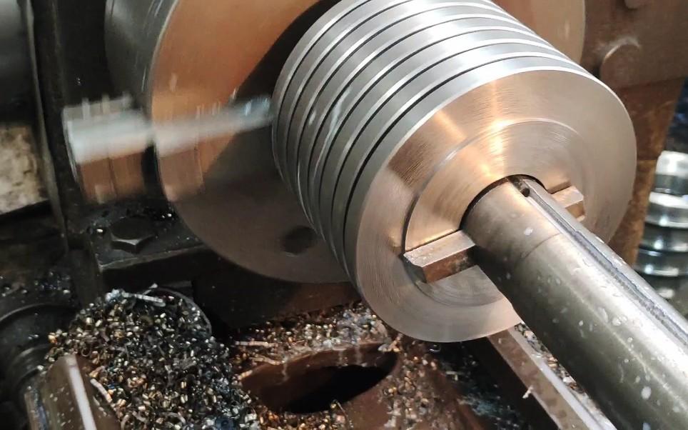
Dans la fabrication mécanique, la précision des alésages internes détermine directement la durée de vie des équipements et la fiabilité des assemblages. Lorsque les alésages initiaux issus du perçage, de la fonderie ou du forgeage ne répondent pas aux exigences fonctionnelles finales, l'alésage devient le procédé essentiel pour corriger le diamètre, la géométrie et la précision de positionnement des alésages. Cet article traite de manière systématique des principes techniques, des classifications des procédés, des systèmes d'outillage, du contrôle des tolérances, des problèmes courants et des stratégies de sélection en matière d'alésage. Il fournit aux ingénieurs une référence pratique et exploitable.
1. L'essence et la valeur fondamentale de l'usinage par alésage
L'alésage est un procédé d'usinage par enlèvement de matière. Il utilise un outil de coupe à pointe unique — généralement monté sur une barre d'alésage — pour retirer la matière couche par couche d'un alésage préexistant. Cette opération permet d'agrandir et de finir le diamètre de l'alésage. L'alésage initial peut provenir d'un perçage, d'un moulage, d'un forgeage ou d'un usinage d'ébauche. Les opérateurs l'usinent ensuite pour obtenir les dimensions et la précision géométrique requises à l'aide d'un tour, d'un centre d'usinage, d'une aléseuse à coordonnées ou d'une aléseuse dédiée.
L'intérêt principal de l'alésage va bien au-delà du simple agrandissement d'un alésage. Elle corrige systématiquement les écarts de circularité, de rectitude, de concentricité et de position. Elle établit également des relations de coordonnées précises entre le trou et les autres caractéristiques fonctionnelles de la pièce. Pour les surfaces d'accouplement critiques telles que les logements de roulements, les alésages de bagues et les faces d’étanchéité, ces propriétés géométriques priment souvent sur le diamètre nominal lui-même.
1.1 Indicateurs clés améliorés grâce à Boring
Précision du diamètre des alésages: Agrandit avec précision le trou initial pour atteindre les dimensions prévues, avec des tolérances contrôlables au micromètre près
Rondeur: Élimine l'ovalisation, les formes polygonales et autres défauts de forme résultant du perçage ou du moulage
Rectitude: Corrige la courbure et la déviation de l'axe du trou, garantissant ainsi une régularité sur toute la longueur des trous profonds
Concentricité / précision de positionnement: Aligne avec précision l'axe du trou par rapport aux surfaces de référence ou à d'autres systèmes de trous
Rugosité de surface: Permet d'obtenir une qualité de surface interne uniforme et contrôlable, répondant aux exigences en matière d'étanchéité et d'ajustement glissant
1.2 Lorsque l'alésage est nécessaire
L'alésage est la solution privilégiée lorsqu'un alésage existant présente un diamètre insuffisant, un défaut de circularité, un désalignement de l'axe ou une précision de positionnement inadéquate. De plus, les alésages préfabriqués ou pré-forgés disposant d'une marge d'usinage suffisante constituent des candidats idéaux pour l'alésage. Ils permettent aux opérateurs d'obtenir un diamètre final contrôlable.
Parmi les applications typiques, on peut citer les paliers, les alésages de boîtes de vitesses, les blocs de vannes hydrauliques, les carters de moteurs, les blocs-moteurs et les montages de précision. Il convient de souligner que les simples trous de passage soumis à des tolérances lâches peuvent ne nécessiter qu’un perçage. Si l’alésage n’apporte aucune amélioration fonctionnelle significative, il ne fait qu’allonger la durée d’usinage et augmenter les coûts.
2. Le déroulement du processus d'alésage
Le processus d'alésage spécifique dépend de la profondeur et du diamètre du trou, du matériau, de l'état initial et des exigences de tolérance finales. Les pièces simples peuvent ne nécessiter qu'une seule passe d'alésage. Les composants de précision nécessitent généralement une séquence en plusieurs étapes comprenant l'alésage de dégrossissage, l'alésage de semi-finition et l'alésage de finition.
2.1 Préparation et fixation de la pièce à usiner
Avant de commencer l’alésage, les opérateurs doivent positionner la pièce sur la surface de référence appropriée et la serrer solidement. La précision du montage est essentielle. L'outil d'alésage suit l'axe prédéfini de la machine. Si le repère de la pièce ou son serrage est mal aligné, même un alésage de dimensions correctes peut se trouver mal positionné par rapport aux sièges de roulements, aux surfaces d'accouplement, aux trous de boulons ou à d'autres éléments.
Par ailleurs, le trou initial doit présenter une surépaisseur suffisante. L'alésage ne permet de corriger efficacement les déviations d'axe et les erreurs géométriques que lorsque la matière restante forme une paroi de trou entièrement nouvelle. Une surépaisseur insuffisante laisse les défauts d'origine partiellement non éliminés. Une surépaisseur excessive augmente les charges de coupe et la durée d'usinage.
2.2 Alésage de dégrossissage et alésage de semi-finition
La tâche principale de l'alésage de dégrossissage consiste à éliminer la majeure partie de l'excédent de matière. Il convient au nettoyage des surfaces moulées, à l'élimination des importantes surépaisseurs d'usinage et à la mise à niveau des alésages initiaux irréguliers pour les rapprocher de la géométrie cible. L'étape d'alésage de dégrossissage ne vise pas la précision finale. Elle établit plutôt des conditions de base uniformes et stables pour les opérations suivantes.
Pour les pièces soumises à des exigences de précision strictes, l'alésage de semi-finition fait office de passerelle entre l'alésage de dégrossissage et l'alésage de finition. Il préserve une surépaisseur de finition uniforme. Cela permet de réduire le volume de matière à enlever lors de la passe d'alésage finale. Il stabilise également les forces de coupe, diminue le risque de déviation de l'outil et crée les conditions idéales pour l'alésage de finition.
2.3 Alésage de finition et alésage de précision
L'alésage de finition permet d'obtenir le diamètre d'alésage final, la concentricité et la qualité de surface souhaités en enllevant un minimum de matière. La profondeur de coupe étant extrêmement faible, la rigidité de la barre d'alésage, la stabilité de la machine, le contrôle du décalage de l'outil et la suppression des vibrations deviennent des facteurs déterminants pour la qualité de l'usinage.
L'alésage de précision trouve de nombreuses applications sur les surfaces d'accouplement critiques telles que les sièges de roulements, les alésages de support d'arbres et les zones d'étanchéité. Des équipements CNC stables et des têtes d'alésage de précision garantissent le respect de tolérances strictes sur le diamètre d'alésage. Cependant, le résultat final reflète toujours les effets combinés de la géométrie du trou, des propriétés du matériau, du porte-à-faux de l'outil, de la stabilité thermique et de l'état de la machine. Par conséquent, les opérateurs doivent planifier le contrôle final en fonction des exigences fonctionnelles plutôt que d’objectifs de tolérance arbitraires.
Barre d'alésage de précision avec plaquettes en carbure indexables — la rigidité de la barre détermine directement la précision d'usinage
3. Principaux types de forage et choix du matériel
Il existe de nombreux types de machines d’alésage. Cependant, la logique fondamentale qui sous-tend les décisions de production repose toujours sur les dimensions de la pièce, l’orientation du trou, la profondeur du trou, l’espace de travail disponible et les exigences en matière de précision de positionnement. L’objectif du choix d’une machine est de trouver une configuration qui assure à la fois un maintien sûr de la pièce et de l’outil, et qui permette à l’outil de coupe d’accéder de manière fiable au trou.
3.1 Forage horizontal et forage vertical
Forage horizontal La broche est disposée horizontalement. Cette configuration est particulièrement adaptée aux grands boîtiers, aux éléments de structure, aux alésages longs et aux pièces présentant de multiples caractéristiques internes. Elle permet de supporter des pièces de grande taille tout en contrôlant avec précision la position d'usinage via la broche ou la table. Il s'agit d'une solution éprouvée pour l'usinage de précision à grande échelle.
Forage vertical convient mieux aux pièces volumineuses et lourdes. Ces composants sont plus faciles à soutenir et à positionner sur une table de travail horizontale. La gravité contribue à maintenir la pièce à usiner stable. Cela simplifie le serrage et la manipulation des grandes pièces circulaires ou de type boîtier.
En production réelle, les opérations sur aléseuse concernent principalement les grandes pièces moulées, les boîtes de vitesses, les châssis d’équipements et autres pièces similaires. Ces composants partagent une caractéristique commune : ils doivent conserver la précision des alésages et les relations de position sur une grande zone de la pièce.
3.2 Alésage de précision et alésage au gabarit
Alésage de précision vise à obtenir un diamètre, une géométrie et un état de surface contrôlables avec précision. Lorsque les alésages dégrossis de manière conventionnelle ne permettent pas de répondre directement aux exigences du plan, l'alésage de précision constitue la solution standard.
Forage au gabarit met particulièrement l'accent sur la précision de positionnement des alésages et sur les relations spatiales entre les éléments. Ce procédé s'applique à l'outillage, aux montages, aux composants de matrices, aux boîtiers de précision et aux pièces nécessitant le positionnement précis de plusieurs alésages par rapport à des repères établis.
La distinction entre ces deux techniques est d’ordre fonctionnel. L’alésage de précision met l’accent sur la qualité du trou lui-même. L’alésage au gabarit offre une valeur inestimable lorsque la précision de positionnement est tout aussi cruciale.
3.3 Procédés de forage spécialisés
Lorsque deux trous ou plus doivent partager un axe commun, alésage coaxial est nécessaire. Parmi les applications courantes, on peut citer les supports de roulements, les carters d'équipements et les grands ensembles structurels. Lorsque l'accès direct à l'usinage depuis le côté opposé à une ouverture existante est limité, alésage arrière peut produire la caractéristique requise de ce côté-là. De plus, alésage aveugle et micro-alésage répondre à d'autres exigences géométriques spécifiques.
Ces procédés spécialisés ont chacun des cas d'application distincts. Les ingénieurs doivent les choisir en fonction de l'accessibilité à l'usinage, des exigences d'alignement ou des besoins géométriques. Ils ne doivent pas les considérer comme des variantes interchangeables d'une même opération.
4. Les systèmes d'outillage de perçage expliqués
La précision de l'alésage dépend fortement des performances du système de coupe. L'outil doit atteindre la profondeur requise tout en maintenant le tranchant en contact stable avec la surface du trou. Il doit le faire sans subir de déformation par flexion excessive. Pour la plupart des opérations d'usinage CNC, les éléments essentiels comprennent la barre d'alésage, la tête d'alésage ou le système de réglage, les plaquettes et l'équipement de contrôle associé.
4.1 Barres d'alésage et têtes d'alésage
La barre d'alésage soutient l'arête de coupe à l'intérieur du trou. Son diamètre, son matériau, sa longueur et son porte-à-faux influent directement sur la rigidité du système. Un porte-à-faux excessif est l'une des causes les plus courantes de la dégradation des performances d'alésage. À mesure que la longueur non soutenue augmente, la barre devient plus sensible à la déviation élastique et aux vibrations. Cela entraîne un conique, des irrégularités de diamètre et des marques de vibration.
Par conséquent, le choix de la barre d'alésage doit respecter le principe suivant : “ diamètre le plus grand possible, longueur la plus courte possible ”. Cela permet d'optimiser la rigidité dans les limites imposées par la géométrie de l'alésage. Les têtes d'alésage de précision permettent un réglage du diamètre au micromètre près pour les opérations de finition. Lors de l'alésage de finition, même les plus infimes variations de décalage ont un impact significatif sur les cotes finales.
4.2 Plaquettes de coupe
Le choix des plaquettes dépend du matériau de la pièce, de la charge de coupe, de la géométrie du trou et des exigences en matière de finition de surface. Les géométries à arête de coupe vive et à angle de coupe positif réduisent les forces de coupe radiales. Cela constitue un avantage particulier lorsque la rigidité de la barre d’alésage est limitée. Pour les matériaux difficiles à usiner, les ingénieurs ont besoin de plaquettes en carbure résistantes à l’usure ou revêtues afin de maintenir la stabilité de l’arête de coupe.
L’objectif du choix des plaquettes ne se limite pas à maximiser la durée de vie de l’outil. Plus important encore, les plaquettes doivent générer des forces de coupe prévisibles. Cela garantit que la déviation de l’outil et le diamètre de l’alésage restent stables et constants tout au long du processus d’usinage.
4.3 Outils de mesure et de contrôle
Les inspecteurs peuvent vérifier le diamètre de l'alésage à l'aide de jauges d'alésage internes, de micromètres d'intérieur ou de machines de mesure par coordonnées. La méthode choisie dépend de la taille du trou, de sa tolérance, de sa profondeur et des exigences du plan. Il convient de souligner que la simple mesure du diamètre est souvent insuffisante. L'alésage de précision peut également nécessiter la vérification de la précision de positionnement, du faux-rond, de la circularité, de la rectitude ou de la concentricité par rapport à d'autres alésages. Par conséquent, le plan de contrôle doit refléter les spécifications fonctionnelles plutôt que de se limiter à la mesure des caractéristiques les plus faciles à évaluer.
5. Tolérances d'alésage et contrôle de la précision
Les performances d'un alésage de précision ne peuvent pas être définies uniquement par la tolérance de diamètre. Son fonctionnement dépend souvent des effets combinés de la taille, de la circularité, de la rectitude, de la précision de positionnement, de la concentricité et de l'état de surface. Cela revêt une importance particulière pour les interfaces entre roulements et arbres. Même si la taille de l'alésage est correcte, une géométrie défectueuse peut tout de même entraîner des difficultés d'assemblage ou des anomalies de rotation.
5.1 Diamètre d'alésage et tolérances d'ajustement
La tolérance requise pour un alésage dépend du type de composant qui y sera monté. Les roulements, les bagues, les goupilles, les arbres et les composants à ajustement serré ont chacun des exigences d’ajustement différentes. Par conséquent, les ingénieurs doivent choisir entre des ajustements avec jeu, des ajustements de transition et des ajustements serrés en fonction des conditions réelles de montage, des charges, des températures, des matériaux et des exigences de service.
Dans des conditions stables, l'alésage CNC permet d'obtenir un contrôle rigoureux du diamètre. Cependant, il n'est généralement pas rentable d'appliquer la tolérance la plus serrée possible à chaque alésage. Les surfaces d'accouplement critiques nécessitent un contrôle rigoureux. Les alésages à jeu ordinaires ne nécessitent pas d'usinage excessif.
5.2 Circularité et rectitude
Les trous percés peuvent présenter un conique, une déviation ou des formes irrégulières. La coulée entraîne encore davantage d’écarts. L’alésage permet d’améliorer ces conditions grâce à une trajectoire de coupe mieux contrôlée qui enlève de la matière. Cependant, pour l’usinage de trous profonds, la longueur de coupe de l’outil devient de plus en plus critique. La déviation de la barre d’alésage peut entraîner une variation du diamètre de l’alésage sur toute la longueur du trou.
Il convient donc d’évaluer la circularité et la rectitude indépendamment du diamètre. Une seule mesure effectuée en un seul point ne permet pas de confirmer si la géométrie globale du trou est acceptable. Une détection multipoint sur toute la longueur du trou est indispensable.
5.3 Concentricité et précision de positionnement
Lorsque plusieurs alésages supportent le même arbre rotatif, ou lorsqu’un alésage doit correspondre précisément à une autre caractéristique de référence, la concentricité et la précision de positionnement deviennent essentielles. L’outil d’alésage coupant par rapport à l’axe de la machine, il peut corriger certaines erreurs de positionnement de l’alésage initial si une marge de matière suffisante est conservée. Cela rend l’alésage particulièrement adapté aux paliers, aux composants de boîtes de vitesses, aux carters de moteurs et aux assemblages à trous multiples.
Lorsque plusieurs alésages doivent partager un axe fonctionnel commun, la stratégie de serrage est souvent aussi importante que le diamètre nominal de l'alésage. La stratégie de fabrication doit donner la priorité aux relations de position entre les alésages. Elle ne doit pas traiter chaque diamètre comme une caractéristique indépendante.
5.4 Finition de la surface interne
L'état de surface interne influe directement sur le coefficient de frottement, les conditions de contact des roulements, les performances d'étanchéité, les caractéristiques de glissement et le taux d'usure. Toutes les applications ne nécessitent pas une surface extrêmement lisse. Il convient de déterminer la rugosité requise en fonction des conditions spécifiques des roulements, des bagues, des joints d'étanchéité, de la lubrification ou d'autres interfaces fonctionnelles.
Lorsque le système d'usinage reste stable, l'alésage de finition permet d'obtenir une qualité de surface contrôlable. Si les exigences fonctionnelles dépassent les capacités économiques de l'alésage, vous pouvez envisager des opérations de finition ultérieures telles que le honage ou la rectification intérieure.
6. Facteurs clés influant sur la précision de l'alésage
La rigidité du système et la stabilité d’usinage ont une influence considérable sur la précision de l’alésage. Les performances de la machine sont certes importantes. Mais même une machine CNC de haute précision ne peut compenser une barre d’alésage trop souple ou un serrage instable de la pièce. Parmi les variables les plus critiques figurent le porte-à-faux de l’outil, les paramètres de coupe, la rigidité de la machine, les performances thermiques, l’évacuation des copeaux et la qualité du serrage.
6.1 Rigidité de l'outil et porte-à-faux
Une barre d'alésage fonctionne comme une poutre en porte-à-faux. Plus elle s'éloigne du support, plus sa rigidité diminue et plus sa déformation sous l'effet des forces de coupe augmente. C'est la raison fondamentale pour laquelle l'alésage de trous profonds est plus difficile que celui de trous peu profonds pour un même diamètre. Même un léger déplacement de la barre d'alésage modifie le rayon de coupe effectif. Cela influe donc sur le diamètre final de la pièce usinée.
Parmi les mesures efficaces pour améliorer la régularité, on peut citer : l'utilisation d'une barre d'alésage du plus grand diamètre possible, la réduction au minimum de la longueur non soutenue et, si nécessaire, le choix de barres d'alésage à haute rigidité ou amortissant les vibrations.
6.2 Vitesse de coupe, vitesse d'avance et profondeur de coupe
Ces trois éléments de coupe influent directement sur le débit d'enlèvement de matière, les forces de coupe, la production de chaleur, les vibrations, l'état de surface et la durée de vie de l'outil. L'ébauche peut recourir à des paramètres agressifs pour éliminer efficacement la matière. En revanche, l'alésage de finition nécessite des conditions de coupe plus stables. Des charges radiales excessives provoquent une déviation de la barre d'alésage. Des plages de vitesse instables induisent facilement des vibrations.
Il n’existe pas de jeu de paramètres universel pour l’alésage. Vous devez personnaliser les paramètres en tenant compte de manière globale du matériau, de la géométrie de l’outil, de la rigidité de la barre d’alésage, de la puissance de la machine et du diamètre de l’alésage.
6.3 Stabilité de la machine, liquide de refroidissement et contrôle des copeaux
Un serrage rigide de la pièce et un mouvement stable de la broche contribuent à maintenir la relation de position souhaitée entre l’outil et le trou. Le liquide de refroidissement permet non seulement de contrôler la température de coupe, mais facilite également l’évacuation des copeaux. Cela est particulièrement vrai dans le cas de trous profonds où les voies d’évacuation des copeaux sont limitées. Une mauvaise évacuation des copeaux entraîne leur réusinage sur la paroi du trou fini. Cela nuit à la qualité de surface ou accélère l’usure de l’outil.
Lorsque les exigences de tolérance sont strictes, la stabilité thermique est tout aussi cruciale. Les variations de température au niveau de l’outil, de la broche et de la pièce peuvent toutes entraîner des variations dimensionnelles importantes. Ces variations affectent le diamètre final de l’alésage.
7. Matériaux concernés et caractéristiques d'usinage
L'alésage peut être appliqué à une large gamme de métaux et de plastiques techniques. Bien que les principes d'usinage soient fondamentalement les mêmes, les propriétés des matériaux ont une incidence significative sur les forces de coupe, la production de chaleur, l'usure des outils, la formation de bavures et la qualité de surface finale obtenue.
Catégorie de matériaux
Caractéristiques d'usinage
Éléments clés à prendre en compte lors du perçage de serrures
Alliages d'aluminium
Excellente usinabilité, taux d'enlèvement de matière élevé
Contrôle des bords des pièces stratifiées et assurance qualité de la surface
Aciers au carbone / aciers alliés
Haute résistance, large gamme d'applications
Contrôle de la force de coupe et gestion de l'usure des plaquettes
Acier inoxydable
Résistant à la corrosion, forte tendance à l'écrouissage
Suppression du durcissement par écrouage et contrôle thermique
Fonte
Bonne stabilité dimensionnelle, mais abrasif
Compensation de l'usure des outils et contrôle des copeaux
Alliages de titane
Rapport résistance/poids élevé, faible conductivité thermique
Gestion de la concentration de chaleur lors de l'usinage et durée de vie des outils
Contrôle de la formation de bavures et gestion du comportement des matériaux
Plastiques techniques
Léger, résistant à la corrosion
Contrôle de la déformation thermique et gestion de la pression de serrage
L'aluminium permet généralement des taux d'enlèvement de matière élevés. Cependant, le tranchant de l'outil et le contrôle des copeaux continuent d'influencer l'état de surface. Les aciers et les aciers alliés nécessitent une attention particulière aux forces de coupe et à l'usure des plaquettes. L'acier inoxydable peut présenter un durcissement par déformation si l'arête de coupe frotte au lieu de couper proprement. La fonte est couramment utilisée pour l'alésage de boîtiers et de composants mécaniques, mais son caractère abrasif accélère l'usure de l'outil. Les alliages de titane concentrent la chaleur près de la zone de coupe, ce qui rend la stabilité de l'outil et la gestion thermique particulièrement importantes. Il est également possible de réaliser un alésage de précision sur des plastiques techniques, mais il faut contrôler strictement la chaleur et la pression de serrage pour limiter la déformation.
8. Alésage, forage et alésage de finition : principales différences
Le perçage, le forage et l'alésage sont autant de méthodes d'usinage de trous. Mais elles répondent à des problématiques différentes. Considérer ces trois procédés comme interchangeables peut entraîner l'ajout d'opérations superflues ou laisser de côté des aspects géométriques importants. La distinction fondamentale est la suivante : Le perçage permet de réaliser le trou initial, l'alésage permet d'élargir et de rectifier ce trou, tandis que l'alésage de finition sert à effectuer un léger ajustement final du diamètre lorsque le trou initial est déjà suffisamment précis..
Processus
Objectif principal
Enlèvement de matière
Correction géométrique
Fonction type
Forage
Créer le trou de départ
Haut
Limité
Formation du trou initial
Ennuyeux
Agrandir et corriger le trou
Moyen
Fort
Correction de la taille et des axes
Alésage
Finir le trou existant
Faible
Limité
Dimensions finales et surface
Le choix entre l'alésage et l'évasement dépend principalement de l'état du trou existant. Lorsqu'il est nécessaire d'enlever une quantité importante de matière ou de corriger les dimensions, la rectitude, la position ou la concentricité, l'alésage est généralement la meilleure option. L'outil d'alésage suit un axe contrôlé et dispose d'un rayon de coupe réglable. Il peut ainsi remodeler la géométrie plutôt que de se contenter de suivre le trou d'origine. Lorsque la position du trou est déjà correcte et que le diamètre est proche de la cote finale, l'alésage est plus approprié. Il enlève moins de matière et améliore efficacement le diamètre final et l'état de surface.
9. Problèmes courants liés au perçage et leurs solutions
La plupart des défaillances courantes sont des manifestations externes d'instabilité du système, de déviation de l'outil, d'un réglage incorrect, d'une surchauffe ou d'erreurs de fixation. L'identification des schémas de défaillance permet de localiser rapidement les causes profondes. Les trois problèmes les plus courants sont le tremblement, la conicité dimensionnelle et l'écart de position.
9.1 Vibrations et mauvaise qualité de surface
Le « chatter » est un phénomène de vibration auto-excité entre l’outil et la pièce. Il se manifeste sur les alésages usinés sous forme de marques répétitives, de surfaces ondulées, de bruits de coupe et d’une rugosité de surface irrégulière. Un porte-barre trop en porte-à-faux est souvent à l’origine de ce phénomène. Cependant, l’état de la broche, le serrage de la pièce, la géométrie de la plaquette et les paramètres de coupe peuvent également provoquer du « chatter ».
Améliorer la rigidité du système et stabiliser les conditions de coupe permet généralement de résoudre le problème plus efficacement que le simple fait d'ajouter une passe de finition supplémentaire sur un montage instable. Parmi les mesures spécifiques, on peut citer la réduction du porte-à-faux de la barre d'alésage, l'augmentation du diamètre de la barre, l'optimisation des paramètres de coupe, l'utilisation de barres d'alésage amortissant les vibrations et l'amélioration de la rigidité du serrage de la pièce.
9.2 Conicité et écart de diamètre
Une variation du diamètre de l'alésage entre l'entrée et la profondeur du trou peut indiquer une déviation de l'outil, une dilatation thermique, une instabilité de la barre ou une usure de l'arête de coupe. Ce problème est plus marqué dans l'usinage de trous profonds, car la barre d'alésage nécessite un porte-à-faux plus long. Même si la machine suit précisément la trajectoire prédéfinie, un outil flexible peut tout de même se déplacer sous l'effet des charges de coupe.
Des alésages surdimensionnés peuvent également résulter d’un réglage incorrect de l’outil, d’un décalage de l’outil, d’un déplacement de la plaquette ou des conditions de température. Par conséquent, pour les ajustements serrés, vous devez contrôler strictement le décalage de l’outil et mettre en place un mécanisme de rétroaction des mesures en temps réel.
9.3 Écarts de position et erreurs de concentricité
Même si le diamètre de l'alésage est parfaitement correct, le trou peut tout de même s'avérer inacceptable si la position de l'axe central est imprécise. Le choix du repère, le positionnement du dispositif de serrage, l'alignement de la broche et les opérations précédentes ont tous une incidence sur la position finale du trou. Cela est particulièrement critique lorsque le trou doit s'aligner avec un autre siège de roulement ou un composant rotatif.
Pour les pièces de boîtier comportant plusieurs alésages, la stratégie de fabrication doit privilégier la précision de positionnement au sein du système d’alésages. Elle ne doit pas traiter chaque diamètre d’alésage comme une caractéristique indépendante. L’utilisation de repères unifiés, la réalisation de l’usinage de plusieurs alésages en un seul serrage et le recours à des aléseuses à coordonnées constituent autant de moyens efficaces pour garantir la précision de positionnement.
10. Domaines d'application typiques de l'alésage
L'alésage revêt une importance cruciale lorsque les alésages internes remplissent des fonctions mécaniques réelles. Les applications telles que le support de roulements, l'étanchéité, le guidage, l'alignement rotatif et l'assemblage de précision imposent des exigences bien plus élevées en matière d'alésage que les alésages de jeu ordinaires. C'est pourquoi ce procédé est largement utilisé dans les secteurs de l'automobile, des équipements industriels, de l'aérospatiale, des dispositifs médicaux et des équipements énergétiques.
10.1 Construction automobile
Les blocs-moteurs, les carters de boîte de vitesses, les logements de roulements, les composants d'essieux et d'autres pièces du groupe motopropulseur comportent souvent des alésages. Ces pièces nécessitent généralement des alésages qui non seulement contrôlent le diamètre, mais garantissent également la concentricité avec les composants rotatifs ou coulissants adjacents. Une géométrie fiable assure un ajustement correct des roulements, le bon fonctionnement des pistons, l'alignement des arbres et la cohérence de l'assemblage.
10.2 Équipements industriels
Les boîtes de vitesses, les corps de pompe, les composants hydrauliques, les châssis de machines, les compresseurs et les carters de moteur comportent généralement des alésages de précision. Les équipements industriels peuvent fonctionner en continu sous des charges importantes. Ainsi, de légères erreurs d’alignement peuvent entraîner des vibrations, une répartition inégale des charges sur les roulements, l’usure des joints ou une durée de vie réduite. Les grands carters constituent également des applications courantes pour les aléseuses horizontales et les aléseuses. Ces machines peuvent accueillir des pièces de dimensions considérablement importantes.
10.3 Aérospatiale
Les boîtiers, les composants structurels, les systèmes d'entraînement et les ensembles rotatifs utilisés dans le secteur aérospatial peuvent nécessiter des alésages positionnés avec précision pour accueillir des roulements, des goupilles, des arbres ou d'autres interfaces. Le défi réside souvent dans la combinaison d’une géométrie compacte et de matériaux difficiles à usiner, tels que les alliages de titane, l’acier inoxydable ou les alliages à haute résistance. Dans ce secteur, la rigidité des outils et le contrôle thermique revêtent une importance particulière. Les matériaux difficiles à usiner augmentent considérablement les forces de coupe et l’usure des outils.
10.4 Énergie, pétrole et gaz
Les corps de vannes, les ensembles de pompes, les composants de systèmes sous pression et d’autres équipements énergétiques peuvent comporter des alésages de grande taille ou profonds. Dans ces alésages, l’étanchéité, l’alignement et le contrôle dimensionnel sont essentiels. Les matériaux de ces pièces peuvent également être relativement durs ou résistants à la corrosion. Le choix des outils et la stabilité du processus revêtent donc une importance particulière. Dans ces applications, vous devez évaluer la géométrie interne finale en tenant compte des exigences en matière de pression, d'étanchéité, de matériau et d'environnement d'utilisation.
11. Analyse des coûts d'usinage par alésage
Le coût de l'alésage dépend de la difficulté liée à l'usinage et au contrôle de l'alésage requis. Il ne se résume pas à la seule dimension du trou. La profondeur du trou, le matériau, les tolérances, la course de l'outil, l'état de surface, le serrage, le contrôle et le volume de production sont autant de facteurs qui influent sur la durée d'usinage. Des plans qui expriment clairement les exigences fonctionnelles réelles peuvent améliorer considérablement l'efficacité de la planification des processus.
11.1 Influence du diamètre et de la profondeur du forage
Même avec un grand diamètre, l’usinage d’un trou traversant de grande taille peut s’avérer relativement simple. L’usinage d’un trou profond et étroit est en revanche bien plus difficile. L’outil doit en effet s’étendre plus loin de son point d’appui. Un porte-à-faux plus important réduit la rigidité, complique l'évacuation des copeaux et augmente le risque de vibrations ou de conicité. C'est pourquoi la profondeur du trou peut avoir un impact sur le coût aussi important, voire supérieur, à celui du diamètre de l'alésage.
11.2 Incidence de la tolérance et de l'état de surface
Des exigences de tolérance plus strictes imposent un contrôle plus rigoureux de l’outillage, de la température, des décalages et des contrôles. L’alésage de précision des roulements peut nécessiter un dégrossissage, un semi-finissage, un alésage de finition et des mesures détaillées. Les alésages de passage non critiques peuvent ne nécessiter qu’un simple perçage. Par conséquent, l’approche la plus rentable consiste à n’appliquer des exigences strictes que lorsque les tolérances ont une incidence sur l’ajustement, l’alignement, l’étanchéité, l’usure ou d’autres fonctions mesurables.
11.3 Incidence des matériaux et du volume de production
Les matériaux plus durs ou plus abrasifs augmentent la durée d'usinage et l'usure des outils. Les matériaux thermosensibles ou difficiles à usiner peuvent nécessiter des conditions d'usinage plus prudentes. Le volume de production influe sur la manière dont les coûts liés au serrage, à la programmation, à l'outillage et au contrôle sont amortis. L'outillage dédié représente une part importante dans le prototypage, mais une part bien moindre dans les lots de production en série. Cependant, l'augmentation du volume ne réduit en rien l'importance de la stabilité du processus. Pour garantir que le même alésage sur plusieurs pièces respecte les tolérances, il est essentiel de disposer d'un outillage et d'un contrôle cohérents.
12. Cadre décisionnel pour le choix d'un procédé d'alésage
Le choix d'une stratégie d'alésage doit partir des exigences fonctionnelles du trou final, et non de la machine elle-même. La géométrie du trou, sa fonction, sa profondeur, le matériau et ses relations avec d'autres éléments déterminent l'outil et la méthode d'usinage les plus appropriés. Une séquence de planification efficace se présente comme suit :
Évaluation du trou existant → Définition de la géométrie finale → Choix de la méthode de forage → Contrôle de la rigidité du système → Finition dans les tolérances → Vérification fonctionnelle
12.1 Départ à partir de la géométrie du trou
Commencez par déterminer le diamètre de l'alésage, la profondeur du trou, le sens d'avance et s'il s'agit d'un trou borgne ou traversant. Évaluez ensuite l'état initial du trou. Un trou déjà percé dont les cotes sont proches de celles requises nécessite une approche très différente de celle d'une pièce brute présentant d'importantes erreurs de positionnement et une matière brute irrégulière. Vous devez également vérifier dès le début le dégagement de l'outil et le diamètre disponible de la barre d'alésage. Ces éléments influent directement sur la rigidité du système.
12.2 Définition des tolérances fonctionnelles
Ensuite, précisez la fonction réelle du trou. Les trous de passage ordinaires, les logements de roulements, les alésages de douilles, les logements de joints d'étanchéité et les trous de support d'arbres coaxiaux ne nécessitent pas le même niveau de contrôle. Vous devez établir un lien entre la tolérance de diamètre, la circularité, la concentricité, la précision de positionnement et l'état de surface, d'une part, et cette fonction, d'autre part. Cela permet à la fois d'éviter de rechercher une précision inutile sur des surfaces non critiques et de garantir que les interfaces importantes fassent l'objet d'un contrôle efficace.
12.3 Déroulement des matchs et équipement
Enfin, adaptez le déroulement du processus aux dimensions de la pièce et à la précision requise. Pour les éléments internes concentriques sur des pièces rotatives, un tour CNC peut s’avérer très efficace. Les centres d’usinage permettent de réaliser des alésages associés à des surfaces fraisées et à des réseaux de trous. Les grands boîtiers peuvent se prêter davantage à l'utilisation de aléseuses horizontales. L'usinage de précision spécialisé peut recourir à l'alésage de finition ou à l'alésage au gabarit. Le processus d'usinage approprié est celui qui permet d'obtenir de manière fiable la géométrie requise avec un minimum d'opérations superflues.
Foire aux questions
Q1 : Un tour peut-il effectuer des opérations d'alésage ?
Oui. Les opérateurs effectuent couramment des opérations d'alésage sur des tours, en particulier pour réaliser des alésages concentriques à l'axe de rotation de la pièce. La barre d'alésage est montée sur le porte-outil et enlève de la matière de l'alésage existant pendant que la pièce tourne. Les tours à commande numérique sont particulièrement bien adaptés à l'usinage de diamètres intérieurs de précision, de sièges de roulements et d'autres alésages concentriques.
Q2 : Quels outils utilise-t-on pour l'alésage ?
L'outil de base pour l'alésage est une barre d'alésage équipée de plaquettes ou d'une arête de coupe à pointe unique. Lorsque vous avez besoin d'un réglage plus précis du diamètre et d'une plus grande précision, vous pouvez utiliser une tête d'alésage de précision. Vous devez choisir le diamètre de l'outil, sa rigidité, la géométrie des plaquettes et la longueur de porte-à-faux en vous basant sur une évaluation complète du diamètre de l'alésage, de sa profondeur, du matériau et des exigences de tolérance.
Q3 : Quels sont les défis liés au perçage coaxial ?
La difficulté du perçage coaxial réside dans la nécessité de garantir que deux ou plusieurs trous soient alignés avec précision le long d’un même axe. Une course excessive de l’outil, des erreurs de serrage, la rigidité de la machine et la déformation de la pièce influent toutes sur les résultats d’usinage. Un serrage précis, un support stable, un contrôle correct du repère et une inspection minutieuse sont essentiels pour maintenir la concentricité des trous.
Conclusion
La réussite d'un alésage dépend d'un contrôle précis du diamètre, de la circularité, de la rectitude, de la concentricité, de la rigidité de l'outil, de la stabilité de coupe et de l'état de surface. Tous ces paramètres doivent être adaptés à la fonction réelle du trou. Le perçage permet de créer une ouverture. Mais lorsque la pièce finale nécessite une géométrie plus précise, des ajustements contrôlés ou des relations de position fiables entre le trou et d’autres caractéristiques critiques, l’alésage devient un processus clé indispensable.
PartsMastery propose des services d'usinage et de fabrication CNC de précision pour les pièces nécessitant des caractéristiques internes précises, un contrôle dimensionnel rigoureux et un contrôle qualité fiable. Nos capacités de tournage et de fraisage CNC permettent un alésage de précision pour les prototypes et les pièces en petites séries en aluminium, acier, acier inoxydable, titane, plastiques techniques et autres matériaux usinables. Nous accompagnons nos clients tout au long du processus de fabrication, de la conception à la production.