






En pocas palabras, el policarbonato (PC) es un plástico resistente y de alto rendimiento que combina tres ventajas clave: gran resistencia a los impactos, retención fiable de la forma y calidad óptica transparente. De hecho, en el ámbito de la fabricación de precisión, los equipos lo utilizan ampliamente como alternativa más segura al vidrio y a los plásticos frágiles para protecciones de seguridad, ventanas ópticas y piezas estructurales industriales. No obstante, el PC reacciona de forma muy intensa al calor generado durante el corte, y un mecanizado apresurado o no optimizado suele provocar problemas como la fusión, residuos pegajosos en la herramienta, grietas por tensión ocultas y un acabado superficial opaco. Por este motivo, exige un control del proceso más minucioso que la mayoría de los plásticos estándar de uso cotidiano.
En esta guía, analizamos en detalle el sistema completo de mecanizado CNC, la lógica de selección de parámetros, las opciones de acabado superficial y las normas prácticas de diseño para facilitar la fabricación con materiales de PC. Al finalizar, dispondrás de una referencia técnica completa que podrás aplicar desde las primeras fases de desarrollo de prototipos hasta la producción en serie.
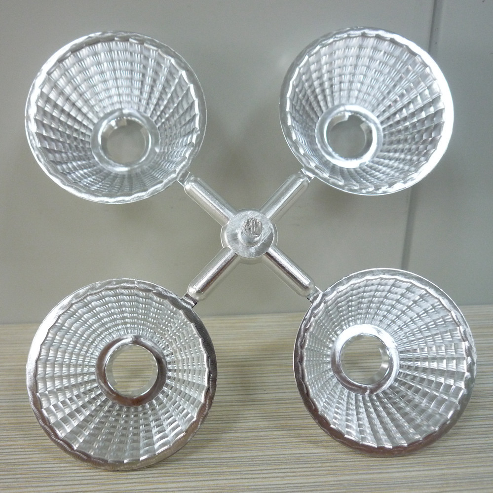
1. Propiedades del material y características de mecanizado del policarbonato
Para obtener resultados uniformes y de alta calidad en el mecanizado de PC, primero hay que comprender cómo se comporta el material bajo las fuerzas de corte y el calor. Estas características fundamentales determinan todas las decisiones del proceso de mecanizado y se clasifican en cuatro categorías principales:
- Excelente resistencia al impacto: A temperatura ambiente, el PC tiene aproximadamente 10 veces más resistencia al impacto que el acrílico. A diferencia de otros plásticos más frágiles, resiste las astillas y las grietas sometidas a fuerzas de corte y sujeción, por lo que ofrece un amplio margen de seguridad para las piezas estructurales que soportan carga.
- Retención fiable de la forma: Las variaciones normales de temperatura provocan cambios mínimos en las dimensiones de las piezas de PC. Tras el mecanizado, la variación dimensional sigue siendo mínima, por lo que es posible mantener de forma fiable tolerancias de precisión en el rango de ±0,02 mm para aplicaciones de montaje de alta precisión.
- Alta sensibilidad al calor: El PC comienza a ablandarse a unos 150 °C. Si se acumula demasiado calor de corte en un punto concreto, el material se ablanda rápidamente, se funde y se adhiere a la herramienta, lo que deja marcas de arrastre en la superficie y hace que los bordes se fusionen entre sí.
- Nivel de nitidez ajustable: El material de PC sin tratar puede alcanzar una transmisión de luz de hasta 89%. Tras el mecanizado, se puede recurrir al posprocesado para recuperar un acabado cristalino, o bien dejarlo con una textura superficial mate o semitransparente.
PC frente a acrílico (PMMA): comparación de propiedades de mecanizado
A continuación, resulta útil establecer una comparación directa entre el PC y el acrílico (PMMA), otro plástico transparente muy habitual. Estos dos materiales se rigen por normas de mecanizado muy diferentes, y utilizar la misma configuración para ambos casi siempre dará lugar a defectos.
| Dimensión del rendimiento | Policarbonato (PC) | Acrílico (PMMA) |
|---|---|---|
| Ventajas principales | Alta tenacidad, resistencia al impacto y mayor resistencia al calor | Alta dureza, fácil pulido, claridad óptica superior |
| Riesgos principales del mecanizado | Fusión por calor, acumulación de residuos en las herramientas, agrietamiento por tensión | Desgaste de los bordes, fracturas, grietas provocadas por la vibración |
| Estrategia de corte | Baja velocidad del husillo, alta velocidad de avance y control riguroso de la temperatura | Alta velocidad del husillo, baja velocidad de avance, cortes limpios y precisos |
| Aplicaciones típicas | Protecciones de seguridad, estructuras portantes, ventanas resistentes a los impactos | Paneles decorativos, escaparates, componentes ópticos de baja carga |
En resumen, para piezas de uso ligero en las que prima el aspecto estético, el acrílico ofrece una gran transparencia a un coste menor. Por el contrario, el PC se convierte en la opción clara cuando la dureza, la resistencia al impacto y la tolerancia al calor son requisitos imprescindibles para los componentes de seguridad y estructurales.
2. Cinco procesos básicos de mecanizado CNC y aspectos técnicos clave
En función del tipo de materia prima y de la forma final de la pieza, puedes elegir entre cinco procesos básicos de mecanizado CNC para el PC. Cada uno de ellos tiene sus propias prácticas recomendadas y prioridades de control, por lo que seleccionar el proceso adecuado desde el principio ahorra tiempo y reduce los defectos.
2.1 Fresado CNC
En primer lugar, el fresado CNC es el proceso estándar para bloques de PC y placas gruesas, especialmente para piezas con cavidades complejas, elementos escalonados y formas 3D irregulares. El mayor riesgo en este caso es la acumulación indeseada de calor y una eliminación deficiente de las virutas. Bajo ninguna circunstancia debes dejar que la herramienta permanezca en un mismo punto durante demasiado tiempo, ya que el calor estancado derretirá rápidamente el material y dejará residuos pegajosos en la superficie.
2.2 Torneado CNC
En cuanto a las piezas giratorias, el torneado CNC es la mejor opción para casquillos, manguitos y carcasas cilíndricas fabricadas a partir de barra. Es esencial contar con filos de corte afilados y velocidades de desplazamiento de la herramienta constantes para evitar desviaciones en el diámetro y el empañamiento de la superficie debido a la concentración de calor. En el caso concreto de las piezas de alta precisión, elija siempre barras de material sometidas a un tratamiento de distensión para obtener los resultados más uniformes a largo plazo.
2.3 Perforación de precisión
En lo que respecta a las operaciones de taladrado, los mayores riesgos son la fusión de las paredes del orificio y el astillamiento en el lado de salida. La mayoría de los talleres utilizan carreras de taladrado cortas y repetidas con retracciones periódicas para dispersar el calor, trabajan con velocidades de rotación de la herramienta ligeramente inferiores y dejan espacio suficiente para que las virutas salgan. En el caso concreto de los agujeros profundos, el aire comprimido ayuda a expulsar las virutas para que no se acumulen ni rayen las paredes debido al exceso de calor.
2.4 Trazado y perfilado de chapas
En el caso de las láminas de PC grandes y finas que se utilizan en protectores y paneles, el fresado es el método de procesamiento habitual. Los talleres suelen utilizar un sistema de sujeción por vacío para mantener la lámina plana, lo que evita que se deforme por tensión debido a las abrazaderas mecánicas. La estrategia de corte se basa en profundidades de corte reducidas y avances rápidos para minimizar las vibraciones y las deformaciones debidas al calor.
2.5 Curvado y conformado en caliente tras el mecanizado
El último proceso de la lista principal es el doblado en caliente, que se puede aplicar tras el mecanizado en plano para crear superficies curvas destinadas a protecciones de seguridad arqueadas y carcasas transparentes a medida. El proceso requiere un calentamiento uniforme por encima del punto de reblandecimiento, el conformado sobre un molde adaptado y un enfriamiento controlado con alivio simultáneo de tensiones. Si se realiza correctamente, evita la recuperación elástica y la aparición de grietas en el futuro.
3. Guía para la selección de parámetros de corte y la configuración de herramientas
La clave de todo mecanizado con PC que se precie es una sencilla regla de oro: primero hay que controlar el calor y, después, ocuparse de la eliminación de virutas. Cada decisión que tomes —desde el tipo de herramienta hasta la velocidad de desplazamiento— debe centrarse en reducir el calor y evitar que se acumule en el interior del material.
3.1 Directrices para la selección de herramientas
Elegir la herramienta de corte adecuada marca una gran diferencia tanto en la calidad de la superficie como en la eficiencia del mecanizado. A continuación se indican las pautas fundamentales que hay que seguir para obtener resultados uniformes:
- Material de la herramienta: Las herramientas de metal duro son la primera opción para la mayoría de los talleres, gracias a su gran rigidez y a su excelente retención del filo. Por otro lado, para la creación de prototipos en lotes pequeños, las herramientas de acero rápido funcionan bien, pero hay que tener en cuenta que habrá que volver a afilarlas con mucha más frecuencia.
- Preparación de los bordes: Busca filos de corte pulidos a espejo con un ángulo de inclinación positivo elevado y ángulos de salida elevados. Estos reducen la fricción durante el corte y disminuyen el riesgo de que el material se adhiera. Nunca utilices herramientas astilladas o desgastadas para trabajar el PC, ya que estropearán rápidamente el acabado de la superficie.
- Elección del recubrimiento: La mayoría de los operarios de máquinas evitan los recubrimientos duros estándar en las herramientas de PC, ya que, de hecho, pueden aumentar la adherencia del material. Para obtener cortes más uniformes, es recomendable utilizar herramientas pulidas sin recubrimiento o alternativas con recubrimiento de diamante.
3.2 Principios de control de los parámetros de corte
Para ofrecerte un punto de partida práctico, la tabla siguiente muestra los parámetros típicos de una fresa de metal duro macizo de 6 mm para material PC estándar:
| Etapa de mecanizado | Velocidad del husillo | Velocidad de avance | Profundidad de corte | Objetivo principal |
|---|---|---|---|---|
| Desbaste | 1200–1800 rpm | 1500–2500 mm/min | ≤ 2 mm | Retirada eficaz de material con acumulación controlada de calor |
| Acabado parcial | 1500–2000 rpm | 1200–2000 mm/min | 0,3–0,5 mm | Tolerancia uniforme en el material y dimensiones estables |
| Acabado | 1.800–2.200 rpm | 800–1500 mm/min | 0,1–0,2 mm | Calidad constante del acabado superficial |
En la práctica, la mejor estrategia de parámetros combina velocidades de rotación moderadas con velocidades de desplazamiento relativamente altas. Un desplazamiento rápido de la herramienta reduce el tiempo de contacto entre la fresa y el material, lo que limita la generación de calor directamente en el origen. Por el contrario, las altas velocidades del husillo, combinadas con velocidades de avance lentas, casi siempre provocan la fusión del material, por lo que siempre debes evitar esta combinación.
3.3 Soluciones de refrigeración y evacuación de virutas
En cuanto a la refrigeración y la eliminación de virutas, la mayoría de los operarios prefieren el chorro de aire comprimido para el mecanizado del PC. Este elimina rápidamente el calor de corte y las virutas, y evita que las virutas calientes se adhieran de nuevo a la superficie de la pieza de trabajo. Los refrigerantes a base de agua por inundación suelen dar malos resultados con el PC, ya que los cambios rápidos de temperatura pueden aumentar la tensión interna. Solo en casos especiales, como las operaciones de taladrado profundo, se debe utilizar una refrigeración mínima mediante nebulización.
4. Consejos para el control del mecanizado en función de las diferentes formas del material en bruto
El PC se comercializa habitualmente en tres formatos de materia prima: láminas, barras y bloques. Cada formato requiere una configuración de mecanizado y sujeción ligeramente diferente, por lo que siempre merece la pena adaptar el material a la forma de la pieza.
4.1 Láminas
En la mayoría de los casos, los fabricantes utilizan chapas para fabricar protecciones, paneles y placas de cubierta. En el caso concreto de las chapas grandes y finas, la sujeción mediante mandriles de vacío ofrece los mejores resultados, ya que evita la deformación por tensión provocada por las abrazaderas mecánicas. Al mecanizar chapas finas, se deben mantener profundidades de corte reducidas para evitar vibraciones y ondulaciones en la superficie debidas a fuerzas de impacto excesivas.
4.2 Barras de acero
Las barras son la mejor opción para piezas giratorias y de tipo casquillo. Para piezas de alta precisión, elige siempre barras sometidas a un tratamiento de distensión; las barras estándar suelen sufrir variaciones dimensionales tras el torneado, a medida que se liberan las tensiones internas. Utiliza mordazas blandas para la sujeción, con el fin de aumentar la superficie de contacto, evitar hendiduras en la superficie y impedir que la pieza se deforme y pierda su forma circular.
4.3 Stock en bloque
Para piezas de paredes gruesas y geometrías 3D complejas que requieren una gran eliminación de material, el bloque de material en bruto es la opción habitual. Los cortes profundos generan mucho calor, por lo que se debe utilizar una estrategia de corte por capas con un tiempo de enfriamiento entre cada pasada. Tras un desbaste intenso, recomendamos encarecidamente añadir una etapa de alivio de tensiones antes de pasar al acabado, ya que esto evita deformaciones y grietas posteriores.
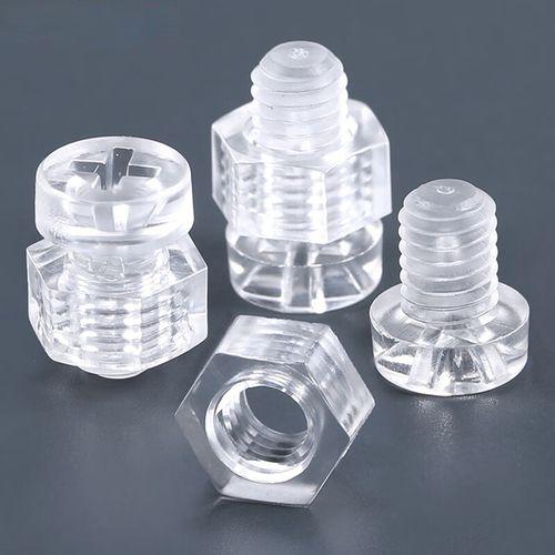
5. Los cuatro principales procesos de acabado de superficies: comparación completa
Una vez finalizado el mecanizado básico, puedes elegir entre cuatro opciones principales de tratamiento superficial para el PC, que se dividen en dos grandes grupos: mejoras estéticas y reducción de tensiones. En función de las necesidades de tu pieza, también puedes combinar varios tratamientos para alcanzar tanto los objetivos funcionales como los estéticos.
5.1 Pulido mecánico
El primer paso de la lista es el pulido mecánico, que utiliza un lijado progresivo y un compuesto de pulido para eliminar las marcas visibles de las herramientas y mejorar la suavidad y el brillo de la superficie. Este método presenta pocas dificultades y unos costes controlables, pero no permite alcanzar una verdadera claridad de grado óptico. En la mayoría de los proyectos, resulta más adecuado para superficies decorativas, áreas funcionales no ópticas y el acabado de bordes. Los operarios deben controlar cuidadosamente la presión y el calor por fricción para evitar el empañamiento de la superficie debido a un sobrecalentamiento localizado.
5.2 Pulido a la llama
A continuación se realiza el pulido con llama, que consiste en pasar rápidamente una llama controlada a alta temperatura sobre los bordes cortados. La capa superficial se refunde brevemente y elimina las marcas de corte, lo que mejora la nitidez de los bordes. El proceso es rápido y económico, por lo que resulta ideal para optimizar el aspecto de los bordes cortados de las chapas. No obstante, el control de precisión es limitado; un exceso de calor provoca el redondeo de los bordes, el amarilleamiento, la aparición de burbujas o pequeñas grietas. Por este motivo, no lo recomendamos para superficies funcionales críticas.
5.3 Pulido con vapores de disolvente
Para conseguir el máximo nivel de claridad óptica, el pulido con vapor de disolvente ofrece, con diferencia, los mejores resultados. El vapor de disolvente disuelve y reorganiza suavemente la capa molecular superficial, alisando los microarañazos y las marcas de herramientas sin apenas alterar las dimensiones. Es el proceso de acabado preferido para ventanas transparentes y componentes ópticos. Para evitar defectos, es necesario controlar estrictamente los parámetros del proceso a fin de prevenir el sobregrabado y el agrietamiento por tensión en las esquinas afiladas y las paredes delgadas.
5.4 Recocido de alivio de tensiones
Por último, el tratamiento térmico suave para el alivio de tensiones es uno de los pasos más importantes para el rendimiento a largo plazo de las piezas, aunque no altere el aspecto de la superficie. Las piezas se calientan hasta una temperatura constante y, a continuación, se enfrían lentamente para liberar las tensiones internas ocultas derivadas del mecanizado, el taladrado y el acabado. Este paso es fundamental para piezas de alta precisión, componentes de pared delgada, piezas de ajuste a presión y piezas expuestas a productos químicos, vibraciones o cargas mecánicas. Mejora la estabilidad dimensional a largo plazo, reduce el riesgo de agrietamiento y ayuda a preservar la claridad óptica con el paso del tiempo.
El ciclo habitual recomendado consiste en mantener la temperatura entre 120 y 125 °C durante 2 a 4 horas (ajustando el tiempo en función del espesor de la pared), seguido de un enfriamiento lento del horno. Para obtener el mejor rendimiento a largo plazo, se recomienda incluir este paso en todas las piezas de precisión, de pared delgada y sometidas a carga.
6. Directrices de diseño DFM para componentes de PC
Un buen diseño orientado a la fabricabilidad resulta muy útil en el ámbito de la informática personal. Reduce los problemas de mecanizado desde el principio, disminuye las tasas de defectos y agiliza la producción. Estas son las reglas de diseño fundamentales que hay que seguir:
- Utiliza esquinas internas redondeadas: Evita las esquinas interiores agudas siempre que sea posible. Recomendamos radios internos de al menos 0,5 mm para evitar la concentración de tensiones y la aparición posterior de grietas. Las esquinas redondeadas también se adaptan a los radios estándar de las herramientas y reducen las operaciones adicionales de acabado de las esquinas.
- Mantener un espesor uniforme de la pared: Las grandes diferencias en el espesor de las paredes provocan una distribución desigual de las tensiones durante el mecanizado y el enfriamiento, lo que da lugar a deformaciones. En lugar de crear escalones bruscos, realiza una transición gradual entre los distintos espesores de las paredes.
- Establece tolerancias realistas: El PC se dilata más que los metales cuando se calienta, por lo que unas tolerancias excesivamente ajustadas encarecen el coste de forma drástica. Una buena práctica consiste en relajar las tolerancias en las superficies no funcionales y especificar por separado la precisión para las caras ópticas y de acoplamiento.
- Indica los puntos de referencia de sujeción: Diseña lengüetas de sujeción planas y continuas o superficies de referencia para que la fijación se mantenga rígida. Esta sencilla medida evita las vibraciones y las desviaciones dimensionales derivadas de una sujeción inadecuada durante el corte.
- Optimizar las características de ensamblaje: Evita las paredes delgadas cerca de los puntos de fijación para prevenir la aparición de grietas debido a las tensiones de montaje. En el caso de los diseños de ajuste a presión, evalúa el riesgo de tensiones desde el principio e incorpora al diseño una medida de alivio de tensiones.
7. Principales aplicaciones industriales de las piezas mecanizadas de PC
Gracias a su combinación única de resistencia y transparencia, las piezas mecanizadas de PC se utilizan en una amplia variedad de sectores. Entre sus aplicaciones más habituales se incluyen:
- Seguridad y protecciones: Protectores de seguridad para máquinas, ventanas protectoras para equipos y barreras transparentes a prueba de explosiones que sustituyen al cristal para mejorar la seguridad en el lugar de trabajo.
- Óptica y ventanas: Ventanas para instrumentos, carcasas para equipos de inspección y soportes para lentes ópticas que combinan una transmisión de la luz fiable con una gran resistencia a los impactos.
- Equipo médico: Carcasas de dispositivos médicos, envases de reactivos y componentes de protección que resisten bien las temperaturas y los productos químicos habituales utilizados en la desinfección.
- Electricidad y electrónica: Carcasas aislantes, soportes para componentes eléctricos y protecciones para equipos de alta tensión con excelentes propiedades de aislamiento eléctrico.
- Estructuras industriales: Componentes para equipos de automatización, plantillas y accesorios de sujeción, y herramientas de inspección que ofrecen un peso reducido y una resistencia estructural constante.
8. Preguntas frecuentes
P1: ¿Cuáles son los defectos más habituales en el mecanizado de PC?
En resumen, los tres problemas más frecuentes son la fusión superficial y la adhesión de la herramienta debido al exceso de calor de corte, la aparición tardía de grietas provocada por tensiones internas retenidas y el empañamiento o amarilleamiento de la superficie debido a un pulido inadecuado. Casi todos estos defectos se pueden evitar: solo se necesitan parámetros de corte optimizados, una etapa específica de alivio de tensiones y procedimientos de posprocesamiento controlados.
Pregunta 2: ¿Cómo se consigue que las piezas de PC mecanizadas recuperen su gran transparencia?
Para conseguir el máximo nivel de transparencia óptica, el pulido con vapor de disolvente es la mejor opción, ya que permite recuperar casi toda la transmisión de luz de la materia prima. Para los bordes y las superficies no críticas, el pulido a la llama funciona bien como opción más rápida y económica. Al trabajar en grandes superficies decorativas, se puede recurrir al pulido mecánico fino para conseguir un acabado semitransparente de alto brillo. Independientemente del método que elijas, recomendamos realizar primero un recocido de alivio de tensiones para reducir el riesgo de agrietamiento.
Pregunta 3: ¿Qué nivel de tolerancia se puede alcanzar en el mecanizado de precisión de PC?
Por regla general, el fresado CNC estándar mantiene de forma constante tolerancias dimensionales de ±0,02 mm. Mediante procesos de precisión estabilizados y un control minucioso, se puede alcanzar una tolerancia de ±0,01 mm para las características críticas. Hay que tener en cuenta que las tolerancias geométricas dependen en gran medida de la geometría de la pieza y del espesor de las paredes; las piezas de paredes delgadas siempre requieren tolerancias adecuadamente más holgadas.
Pregunta 4: ¿Por qué se agrietan espontáneamente las piezas de PC tras el mecanizado?
En casi todos los casos, las grietas espontáneas se producen porque las tensiones de mecanizado no liberadas se acumulan con el tiempo, especialmente ante cambios de temperatura o cargas de montaje. El riesgo es mayor en piezas sometidas a un mecanizado intenso, componentes de paredes delgadas y diseños con esquinas afiladas. La aplicación de un tratamiento térmico suave de alivio de tensiones tras el mecanizado resuelve casi siempre este problema por completo.
Conclusión
En definitiva, el éxito del mecanizado CNC del PC depende tanto de un sólido conocimiento del material como de un estricto control del proceso, con especial atención a la gestión del calor y la reducción de tensiones. Con una selección adecuada del material, unos parámetros bien ajustados y una optimización cuidadosa del diseño, el PC ofrece todas sus ventajas —resistencia al impacto, transparencia y estabilidad dimensional— para la fabricación de componentes de plástico técnico de gran fiabilidad.
PartsMastery se especializa en el mecanizado CNC de precisión de plásticos técnicos y ofrecemos servicios integrales para el policarbonato, desde el desarrollo de prototipos hasta la producción en serie. Proporcionamos una solución integral de personalización que incluye la selección de materiales, la optimización del diseño para la fabricación (DFM) y el acabado superficial, por lo que puede contar con una gran precisión dimensional y la fiabilidad a largo plazo de las piezas en cada proyecto.