


In turbomachinery, turbine blades serve as the core aerodynamic components that enable energy conversion. By interacting with high-temperature, high-pressure fluids, they turn thermal or pressure energy into rotational mechanical energy at the rotor. Across aero engines, industrial gas turbines, and steam turbines, blades vary significantly in structural form, material systems, and manufacturing accuracy depending on operating conditions. The coordinated performance of rotating blades and stationary vanes directly defines the energy efficiency, operational reliability, and service life of the entire unit.
This guide systematically covers turbine blade functions, classifications, structural composition, design principles, material selection, protection technologies, and manufacturing inspection logic. It provides a complete reference framework for engineering design, procurement, and project planning. At PartsMastery, we specialize in precision manufacturing for high-end turbomachinery components. We deliver custom precision machining services for all types of turbine blades, supporting the full project lifecycle from prototype development to spare part production.
1. Core Functions and Basic Classifications
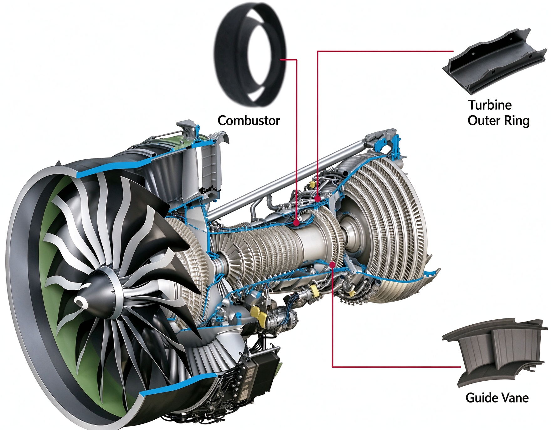
At their core, turbine blades regulate fluid flow and transfer energy. We can classify them by motion type, operating position, working fluid, and energy transfer principle. A single blade often falls into multiple categories at once.
1.1 By Motion Type: Rotating Blades and Stationary Vanes
Rotating blades (buckets): Mounted on the rotor disk, these blades redirect the fluid as it passes through and extract energy to spin the rotor. This rotation then drives compressors, generators, or other loads. The blade root must withstand enormous centrifugal loads and cyclic stresses, so structural strength is the highest priority.
Stationary vanes (nozzle blades / stators): Fixed to the casing or inner housing, they primarily guide and condition the flow before it enters the next row of rotating blades. In certain stages, they also accelerate the flow through nozzle action to boost work output. Stationary vanes experience no centrifugal load, but they still face high thermal and aerodynamic stresses.
1.2 By Pressure Stage: High-Pressure and Low-Pressure Blades
High-pressure stage blades: Located closest to the combustion chamber or steam inlet, these operate at the highest temperatures and pressures. They almost always use heat-resistant alloys with cooling structures, and they are smaller in size. Design priorities focus on high-temperature strength and thermal stability.
Low-pressure stage blades: Located further downstream in the turbine, these run at lower temperatures but handle higher volumetric flow rates, so the blades are longer. Design priorities focus on centrifugal load control, vibration behavior, and water erosion resistance. Some low-pressure applications use low-density titanium-based materials to reduce weight.
1.3 By Working Principle: Impulse and Reaction Blades
Impulse blades: Most of the pressure drop takes place in the stationary nozzles. The resulting high-velocity flow then changes direction across the moving blade row to produce thrust. With little pressure difference across the blade itself, these designs are mechanically simpler and work well for small, high-speed applications.
Reaction blades: The fluid expands and drops in pressure across both the stationary vanes and the rotating blade passages. As a result, the rotor receives thrust from both flow turning and acceleration through the blade channel. This design delivers higher efficiency but creates more complex blade loading, and it is the dominant choice in medium and large gas and steam turbines.
| Classification Dimension | Typical Categories | Core Characteristics |
|---|---|---|
| Motion type | Rotating blades / Stationary vanes | Rotors transfer energy to the shaft; stators guide and condition the flow |
| Pressure stage | High-pressure blades / Low-pressure blades | HP stages focus on heat resistance; LP stages focus on strength and erosion resistance |
| Working principle | Impulse / Reaction | Impulse designs are simpler; reaction designs deliver higher energy efficiency |
| Working fluid | Gas turbine blades / Steam turbine blades | Gas turbines emphasize oxidation resistance; steam turbines emphasize corrosion and erosion resistance |
2. Core Structural Components and Their Design Roles
A complete turbine blade combines an aerodynamic working surface with mounting and structural features. Every region is engineered to support aerodynamic performance, structural strength, and assembly reliability.
2.1 Airfoil
The airfoil is the primary working surface that interacts directly with the fluid. It includes a pressure side, suction side, leading edge, and trailing edge. Its cross-sectional shape, thickness distribution, and curvature profile directly define aerodynamic efficiency. Along the blade span, twist accuracy and profile tolerance are the key metrics that influence overall machine performance.
2.2 Blade Root
The root forms the assembly interface between the blade and the rotor disk, and it carries all structural loads. The most common designs are fir-tree, dovetail, and blisk configurations. Fir-tree roots offer high load capacity and easy installation, making them the standard for heavy-duty gas turbines. Dovetail roots are simpler and common in smaller steam turbines. Blisk designs integrate blades and disk into a single part to eliminate clearance losses, and they appear in high-performance aero engines.
2.3 Platform
Sitting at the transition between root and airfoil, the platform forms the radial boundary of the gas path. It maintains flow path continuity, blocks radial leakage, and also helps optimize stress distribution at the root region.
2.4 Tip and Shroud
The tip is the radial outer end of the airfoil, and the gap between tip and casing directly affects leakage losses. Some blades include a shroud or tip structure that reduces leakage and improves damping for better vibration stability. Unshrouded free-tip designs, by contrast, are simpler and lighter in weight.
3. How Key Design Elements Affect Performance
Turbine blade design requires a multi-objective balance between aerodynamic performance, structural strength, and thermal stability. Each design decision directly shapes efficiency and service life.
3.1 Airfoil Aerodynamic Profile
Inlet and outlet flow angles, surface curvature, and leading/trailing edge radii all determine flow losses and work output. Profile deviation alters incidence angles, which can trigger flow separation, higher losses, and uneven load distribution. Design teams must balance aerodynamic gain with manufacturability: thinner edges may improve flow behavior, but they also increase machining difficulty and in-service risk.
3.2 Spanwise Twist Design
Because circumferential velocity increases from root to tip, the relative flow angle changes along the blade height. Twisting the blade along its span keeps each airfoil section at its optimum angle of attack, which maximizes aerodynamic efficiency across the full span. Short blades usually show less twist, while long low-pressure blades typically require a larger twist angle.
3.3 Strength and Vibration Behavior
Rotating blades experience centrifugal, aerodynamic, and thermal loads simultaneously. Cyclic loading can lead to high-cycle fatigue failure. During design, engineers perform modal analysis on the blade-disk system to avoid resonance ranges. They also optimize root transition fillets to reduce stress concentration risk.
3.4 Tip Clearance Control
Excessive tip clearance increases leakage and reduces efficiency. Insufficient clearance, on the other hand, can cause rub events under hot operating conditions. Designers must balance thermal expansion, centrifugal deflection, manufacturing tolerances, and assembly variation to find the optimal tradeoff between efficiency and safe operation.
4. Common Material Systems and Selection Logic
Material selection is fully matched to operating temperature, load level, and corrosion environment. Blades at different stages use very different material systems.
| Material Category | Typical Grades | Core Performance | Typical Applications |
|---|---|---|---|
| Nickel-Based Superalloys | Inconel 718, GH4169, single-crystal superalloys | High hot strength, creep resistance, oxidation resistance | HP hot-section blades in gas turbines and aero engines |
| Heat-Resistant Stainless Steels | 1Cr13, 2Cr13, martensitic heat-resistant steels | Stable strength, steam corrosion resistance, cost-effective | Medium and low-pressure steam turbine blades, low-temperature industrial turbine stages |
| Titanium-Based Alloys | TiAl intermetallics, Ti-6Al-4V | Low density, high specific strength, good mid-temperature performance | LP turbine stages in aero engines, compressor blades |
Importantly, material selection should never rely on grade name alone. Full specifications must also define heat treatment condition, grain structure requirements, and surface coating standards. Complete material specifications are the foundation of consistent blade performance.
5. Cooling Technologies and Surface Protection Systems
For high-temperature stages, base material properties alone are not enough to meet service requirements. Cooling and coating technologies are required to further raise temperature capability.
5.1 Internal Cooling Structures
Engineers design serpentine passages and rib turbulators inside the blade. Cooling air, usually bled from the compressor, flows through these channels and removes heat through convection, which lowers the base metal operating temperature. Cooling passages are typically formed integrally during the casting process.
5.2 Film Cooling
Dense arrays of tiny cooling holes are machined into the blade surface. Cooling air exits through these holes and forms a cool protective film over the airfoil, insulating the base metal from hot gas. Hole position, inclination angle, and diameter all strongly influence cooling effectiveness. These features are most often produced with laser drilling or electrical discharge machining.
5.3 Thermal Barrier Coatings (TBC)
A ceramic thermal barrier coating is applied to the blade surface. It significantly reduces the metal surface temperature while also improving oxidation and corrosion resistance. Coating thickness and adhesion must be tightly controlled to prevent spallation and failure during operation.

6. Manufacturing Processes and Quality Inspection Essentials
Turbine blade manufacturing combines near-net-shape forming with precision machining. Final accuracy and quality depend on end-to-end process control.
6.1 Blank Forming Processes
Most high-temperature blades start from investment castings. Casting can produce near-net-shape airfoils and integrate internal cooling passages. High-performance blades may also use directional solidification or single-crystal casting to elevate high-temperature performance. Smaller, moderately loaded blades can use forged blanks. Prototypes and spare parts can also be machined directly from solid bar stock using 5-axis methods.
6.2 Precision Machining and Finishing
After blank forming, 5-axis simultaneous machining creates precision mating features such as blade roots, platforms, and mounting datums to guarantee assembly accuracy. Airfoil surfaces receive further refinement through CNC belt finishing or robotic polishing to control surface roughness and profile accuracy.
6.3 Full-Dimensional Quality Inspection
Quality inspection covers three major dimensions: geometric accuracy, surface quality, and material integrity.
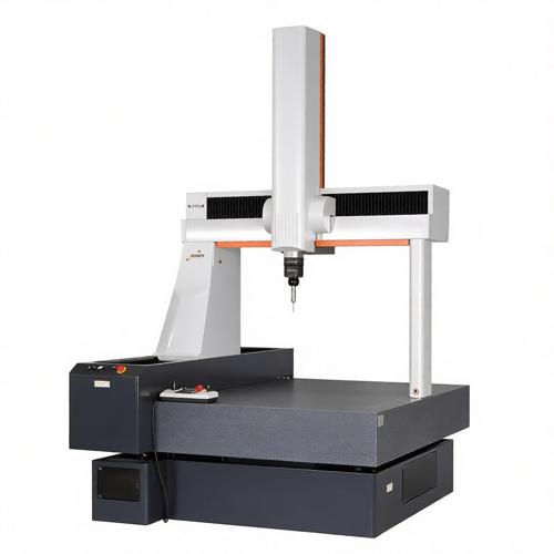
- Geometric accuracy: CMM and optical scanning verify airfoil profile, root dimensions, and geometric tolerances
- Surface quality: Roughness testing and fluorescent penetrant inspection detect surface microcracks
- Internal integrity: Radiographic and ultrasonic testing find internal inclusions, porosity, and other casting defects
- Performance verification: Cooled blades also undergo air flow testing to validate cooling performance
When selecting a turbine blade supplier, teams should define clear project boundaries and evaluate capability across process expertise, quality systems, and relevant experience.
7.1 Define the Manufacturing Scope Up Front
Before a project starts, teams should clarify whether the supplier will deliver fully finished components or only machine customer-supplied blanks. They should also specify whether special operations such as heat treatment, coating, and non-destructive testing are included. Different scopes of supply lead to very different costs and lead times.
7.2 Key Capability Review Points
When evaluating suppliers, focus on proven machining experience with the relevant materials, 5-axis machining and inspection equipment, special process certifications, and quality traceability systems. For safety-critical components, complete material traceability and inspection records matter more than price alone.
7.3 Align Requirements for Consistent Comparison
When comparing multiple suppliers, use the same drawing revision, material standards, and acceptance criteria. This avoids misaligned expectations and makes quotations truly comparable. Any alternative materials or processes should always be reviewed and approved by the engineering team before adoption.
Conclusion
All things considered, turbine blades are the central performance driver of turbomachinery equipment. Their design, materials, manufacturing, and inspection form a multidisciplinary engineering system. Clear classification understanding, rational material selection, and rigorous quality control are the essential prerequisites for efficient, reliable turbine blade service.
With 5-axis precision machining, full-dimensional inspection, and integrated surface treatment capabilities, PartsMastery delivers custom turbine blade manufacturing for industrial turbines and power equipment. We support prototype development, spare part production, and low-volume manufacturing, and we help customers achieve accurate, reliable turbomachinery component implementation.