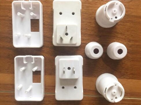
 典型的注塑成型消费电子产品零部件
消费类电子产品的零部件在CAD图纸上可能看起来毫无瑕疵,但在实际制造过程中往往会遇到真正的挑战。壁厚过大会导致缩痕,隐藏式卡扣会增加模具的复杂度,而外壳两半的翘曲则可能导致装配接缝不平整。
优秀的电子产品注塑模具设计需在外观、用户交互、机械强度和生产稳定性之间取得平衡。必须在切割模具钢之前就权衡所有这些因素——而不是在试模期间仓促地去解决这些问题。.
1. 明确零件功能和服务要求
首先应明确注塑件的实际功能。装饰性边框、结构框架和柔性按键虽然可能采用相同的工艺,但它们所需的材料和设计规则却大不相同。.
1.1 按功能对零件进行分类
消费类电子产品的注塑件通常分为以下几类:
- 装饰件: 在保护内部组件的同时确保外观质量
- 结构部件: 承载载荷、固定紧固件或与其他部件配合
- 交互式部分: 按钮、键帽、滑块和电池盖
- 防护部件: 吸收冲击力或阻止碎屑进入敏感区域
- 柔性部件: 提供密封、抓握、缓冲或铰链运动
当一个部件需要承担多种功能时,应明确优先级。例如,一个外壳在支撑螺钉凸台的同时,还需保持外观整洁——如果凸台位置不当,会在可见表面留下压痕。.
1.2 定义服务环境
在选择塑料之前,请记录预期的工作条件:
| 考虑 |
需回答的问题 |
| 温度 |
正常工作温度和最高工作温度分别是多少? |
| 影响 |
它必须经受住多高的跌落高度或多大的载荷? |
| 化学品 |
它会接触清洁剂、油类或化妆品吗? |
| 紫外线照射 |
它是在户外使用,还是会暴露在阳光直射下? |
| 使用寿命 |
预计使用寿命为多少年或多少个工作循环? |
| 维护 |
用户会经常打开或清洁它吗? |
1.3 制定外观与质感标准
请对A级表面进行明确标注。界定可接受的颜色、光泽度、纹理及装配间隙。图纸还应限定浇口、顶出痕迹和分型线可出现的位置。
按键行程、驱动力和外壳刚度均应可测量。诸如“高端手感”之类的模糊描述无法指导生产检验——应将其转化为可量化的规格参数。.
1.4 设定生产和装配目标
预计产量决定了模具材料、型腔数量和自动化程度。可维护性需求则影响连接方式——卡扣、螺钉、嵌件、焊接或粘合剂。
在提交生产审核之前,请汇总预计年产量、装配方法、外观标准和关键尺寸。.
2. 材料选择与成型策略
在详细设计特征之前,应先选择材料。树脂的刚度会影响加强筋的布置,收缩率决定了外壳的对齐情况,而允许应变则决定了卡扣连接能否经受住反复装配。.
2.1 常见消费电子产品塑料的比较
| 材料 |
典型优势 |
需核实的要点 |
| ABS |
外观美观,抗冲击性好,易于成型 |
高温、紫外线和化学物质的暴露 |
| 个人电脑 |
高冲击强度和耐热性 |
成本较高且对化学物质敏感 |
| 聚丙烯 |
耐化学腐蚀性和良好的铰链性能 |
刚度低、收缩率高、附着力差 |
| PA(尼龙) |
强度、耐磨性和耐热性 |
受湿度影响的尺寸变化 |
| TPE / TPU |
抓握力、密封性和柔韧性 |
粘结强度与压缩永久变形 |
以上是对材料系列的概括性描述。最终决定必须基于具体的等级数据。.
2.2 根据产品需求选择合适的材料性能
根据应用场景确定材料性能的优先级。便携式扬声器外壳可能更重视抗冲击性和耐化学性,而显示器边框则可能更注重外观和尺寸稳定性。
填充塑料可以提高刚度,但可能会改变收缩率、表面光洁度以及模具磨损情况。高性能树脂通常需要更高的加工温度和更严格的工艺控制。.
2.3 解决收缩和尺寸稳定性问题
注塑成型后的塑料在冷却过程中会收缩。收缩程度取决于材料、几何形状、浇口位置、纤维取向以及加工条件。
收缩会直接影响外壳接缝、按钮、按扣和定位特征。对于对湿气敏感的材料,需要格外注意,因为成型后尺寸可能会发生变化。您的检验规范应明确说明是测量干燥状态下的零件,还是经过调湿处理后的零件。.
2.4 验证热量和火焰要求
将所选材料的长期热性能与零件周围的预期温度进行对比。短期热测试可能无法揭示长期蠕变或变形现象。
阻燃性能因材料厚度而异。请确认适用的产品标准、测试厚度、颜色以及经批准的材料数据。使用阻燃树脂并不意味着成品自动符合阻燃认证要求。.
3. 部件架构与工具开发方向
产品结构决定了各部件的组装方式,以及每个注塑件如何从模具中脱模。.
3.1 将产品分解为可成型部件
常见的分拆安排包括:
- 上、下外壳
- 前后壳体
- 机身配有独立表圈
- 结构框架上的装饰板
- 独立按钮、外壳和软触感部件
分型线应便于明确的装配顺序,并使接缝远离主要视线区域。将复杂的几何形状移至单独的零件上虽然会增加装配步骤,但可以简化注塑成型工艺。.
3.2 定义外壳拆分与装配方向
检查外壳的闭合方式,以及操作人员能否触及每个紧固件或连接点。内部结构不应在闭合过程中阻碍组装或挤压零件。
可维护产品所需的连接方案与永久焊接外壳截然不同。电池盖还需配备易于开启的卡扣,并能控制释放力。.
3.3 设置分型线和绘图方向
模具开模方向决定了脱模斜度、顶出方式以及大部分底切的处理方式。在确定外观设计之前,应先确定开模方向。
将分型线设置在自然边缘或视觉过渡处。横跨光滑表面的分型线往往会导致表面瑕疵或接缝不齐。侧壁越深、表面纹理越粗糙,脱模阻力就越大。.
3.4 简化倒角以降低刀具成本
与拉伸方向垂直突出的特征可能会阻碍直线顶出。简单的底切可通过关闭装置释放,而较深或封闭的几何结构可能需要侧向动作或顶针。
在添加这些机构之前,请先确认该特征是否能与拉伸方向对齐、能否通过排料孔成型,或者能否移至单独的零件上。结构更简单的模具通常制造和维护成本更低。.
4. 壁厚、拔模角、加强筋和凸台
零件的基本几何形状决定了填充、冷却、顶出以及尺寸稳定性。.
4.1 保持壁厚均匀
壁厚不均匀的壁体冷却速度各不相同。较厚的区域可能会出现凹陷或气孔,而较薄的部分则可能在型腔完全填满之前就已凝固。
没有一种通用的壁厚适用于所有情况。合适的壁厚取决于树脂牌号、流道长度、刚度、抗冲击性以及外观要求。当壁厚必须变化时,应采用渐变过渡。将较厚的边缘、安装垫片、支脚和凸台掏空,而不是保持实心。.
4.2 添加草图和圆角
与拉伸方向平行的表面需要拔模斜度。拔模斜度不足会在顶出过程中导致拖痕或零件变形。较深或纹理较明显的表面通常需要更大的拔模斜度——在确定外观设计之前,请务必确认这些参数。
尖锐的内角会集中应力并限制熔体流动。圆角过渡可改善模具的填充性、抗冲击强度和可加工性。.
4.3 在不损伤外壳的情况下添加加强筋
肋条可在不增加壁厚的情况下提高刚度。应将其方向与预期载荷方向保持一致。
肋条过厚可能会在相对表面留下缩痕。过高且过细的肋条可能难以填充。应采用适当的根部圆角和脱模斜度,并避免多根肋条交汇处形成复杂的交点。.
4.4 设计坚固的螺纹凸台
螺钉凸台应为中空结构,并采用加强筋或加强板进行加固。实心凸台会积聚热量,可能导致外表面出现凹陷。
需检查螺柱壁厚、与外观表面的距离、螺钉咬合深度、导向孔几何形状、安装扭矩以及预计的拆卸循环次数。应按照螺钉供应商的指导,使用生产用树脂验证最终几何形状。.
5. 组装与用户交互功能
装配特性直接影响生产效率以及用户对成品的使用体验。.
5.1 选择合适的连接方法
| 加入方式 |
最适合 |
主要局限性 |
| 卡扣式安装 |
快速、无需工具的组装 |
疲劳和滞留问题 |
| 自攻螺钉 |
拆卸频率较低的产品 |
螺纹磨损与扭矩变化 |
| 金属嵌件 |
需要反复维护的产品 |
添加一个插入操作 |
| 超声波焊接 |
永久性住房关闭 |
需要受控的接头几何形状 |
| 粘合剂 |
不规则接头或不同材料接头 |
固化控制与棘手的修复 |
5.2 设计可靠的卡扣连接
卡扣的配合性能取决于材料的应变、梁长、厚度、根部半径以及锁紧几何形状。一个短而厚的卡扣虽然看起来很坚固,但其根部可能会承受非常高的应力。
应采用平滑的导入斜面,并预留足够的装配间隙。对于需投入实际使用的产品,应针对预期的开启循环次数和温度范围对卡扣进行测试。.
5.3 按钮、键帽和电池盖
按钮需要留有足够的间隙,以避免因工装公差和装配错位导致的摩擦。另一方面,间隙过大则会产生明显的缝隙或侧向间隙。
应使用导向特征来控制运动方向,同时避免对按钮施加过度的约束。在完成环境和耐久性测试后,需验证按压力、复位行为及行程路径。电池盖需要控制好卡扣力并采用防误装设计,此外还需验证铰链或卡扣在预期开启次数下的使用寿命。.
5.4 控制箱的对齐与间隙
使用专用的定位特征来对准配合的外壳。螺钉可提供夹紧力,但不应作为唯一的对准方法。
台阶接合或榫槽接合可改善对准效果并隐藏直接接缝,但过紧的公差可能会导致卡死。应明确关键位置的可接受间隙和平整度要求。公差分析应涵盖壳体部件、定位特征、紧固件安装顺序以及装配变形。.
5.5 包覆成型设计
包覆成型适用于握把、柔性按钮、密封件和受冲击区域。刚性基材与软性材料必须具有相容性。
仅靠化学键合可能不够,因此通常需要机械锁合。设计还必须控制飞边、夹紧力、包覆成型厚度以及材料交界处的外观。.
6. 外观控制与生产验证
一个注塑件可能通过尺寸检查,却未能通过外观验收。应分别制定并记录外观和功能的标准。.
6.1 型腔、焊缝和顶出痕迹
浇口位置会影响充填、缩水以及焊线的位置。尽可能将焊线避开受载的按扣和主要外观区域。将顶针设置在隐蔽且支撑良好的表面上。在确定几何形状和树脂后,应重新审视这些决策。.
6.2 质感、色彩与装饰
纹理越深,越能掩盖细微瑕疵,但需要更大的拔模角。高光泽表面会放大划痕、流痕和抛光差异。
应在受控光照条件下,参照标准样本确认颜色是否合格。对于喷涂、印刷或激光标记,需明确定位公差、表面处理、附着力及耐磨性要求。.
6.3 构建和测试原型
原型有助于验证人体工学设计、按钮操作、紧固件间隙、装配顺序以及外壳接缝。3D打印或铸造件无法完全再现注塑收缩、表面质量或疲劳行为。应先使用它们检查装配适配性和功能性,然后通过注塑样品确认生产性能。.
6.4 模具制作前的DFM审查
在切割工具钢之前,请确认以下事项:
- 壁厚、拔模角、加强筋、凸台和卡扣
- 倒角和分型线
- 闸门、通风口、冷却和排气
- 关键尺寸与检验方法
- 工具材料及预计用量
PartsMastery 提供注塑成型、嵌件注塑、包覆成型、模具制造、DFM 审查以及模流分析服务。在开始切削加工之前,通过模具制造前的审查,可识别几何形状和模具制造方面的风险。.
6.5 T1 和试生产检验
T1检验应涵盖尺寸和已批准的外观要求。试生产旨在验证工艺和装配在多个零件上是否保持一致。关键检查项目包括:
- 外观: 表面处理、翘曲和外壳间隙
- 装配: 螺钉扭矩、啮合和装配时间
- 功能: 按键行程和抗下坠性
7. 关键要点
成功的注塑成型始于明确的产品和材料要求。在详细设计各个特征之前,应先确定零件结构和拉线方向。
原型件用于验证人体工学和装配性。此后,制造可产性设计(DFM)、首模(T1)和试生产必须确认注塑工艺及批量生产的稳定性。
如果您的设计已准备好进行模具制造,请将CAD模型连同目标材料、年产量、外观要求和关键尺寸一并发送给PartsMastery。工程评审可在模具制造开始前发现潜在风险。.
常见问题解答
对于消费电子产品零部件而言,注塑成型在什么产量下才划算?
当批量生产、外观一致性以及较低的单位成本能够抵消初始模具投资时,注塑成型就具有了吸引力。在比较各种工艺时,应以预计的总生产量为依据,而不仅仅是首笔订单的数量。.
在模具制作开始后,设计还能做多大程度的修改?
通常可以进行一些不影响钢材安全的微小修改。但移动分型线、修改大面积曲面或去除底切,可能需要使用镶块或进行大量返工。在模具发货前,请锁定关键接口。.
进行DFM评审需要哪些信息?
请提供3D CAD模型、图纸、材料要求、预计产量、表面光洁度、纹理、颜色以及关键尺寸。同时,请标注浇口、顶针、分型线或可见缺陷等受限区域。.
在批量生产前,你们是如何批准外观标准的?
在受控光照条件下,使用实物色样、质感样和缺陷限值样。记录可接受的光泽度偏差、焊缝线、浇口痕迹、划痕和外壳间隙,然后将批准的样本作为生产参考。.






