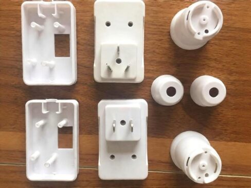
Typical injection molded consumer electronics components
Consumer electronic parts may look flawless on a CAD drawing, but manufacturing them often brings real challenges. Overly thick walls cause sink marks, hidden snaps drive up tool complexity, and warped housing halves can leave uneven assembly seams.
Good injection molding design for electronics balances appearance, user interaction, mechanical strength, and production stability. You must weigh all these factors before cutting tool steel — not scramble to fix them during tryout.
1. Define Part Function and Service Requirements
Start by clarifying what the molded part actually does. A cosmetic bezel, structural frame, and flexible button may share the same process, yet they demand very different materials and design rules.
1.1 Classify Parts by Function
Consumer electronic injection molded parts typically fall into these categories:
Cosmetic parts: Control visual quality while protecting internal components
Structural parts: Carry loads, hold fasteners, or mate with other parts
Interactive parts: Buttons, keycaps, sliders, and battery covers
Protective parts: Absorb impact or block debris from sensitive areas
Flexible parts: Provide sealing, grip, cushioning, or hinge motion
When one part serves multiple roles, set a clear priority. For example, a housing may need to support screw bosses while keeping the exterior clean — poorly placed bosses leave sink marks on visible surfaces.
1.2 Define the Service Environment
Before selecting a plastic, document the expected operating conditions:
Consideration
Questions to Answer
Temperature
What are the normal and maximum operating temperatures?
Impact
What drop height or load must it survive?
Chemicals
Will it contact cleaners, oils, or cosmetics?
UV exposure
Will it be used outdoors or in direct sunlight?
Service life
How many years or operating cycles are expected?
Maintenance
Will users open or clean it frequently?
1.3 Set Appearance and Feel Standards
Mark Class A surfaces clearly. Define acceptable color, gloss, texture, and assembly gaps. The drawing should also restrict where gates, ejector marks, and parting lines may appear.
Button travel, actuation force, and housing stiffness should all be measurable. Vague descriptions like “premium feel” cannot guide production inspection — translate them into quantifiable specs.
1.4 Set Production and Assembly Targets
Estimated volume drives tool material, cavity count, and automation level. Serviceability needs influence the joining method — snaps, screws, inserts, welding, or adhesive.
Before submitting for production review, compile the estimated annual volume, assembly method, appearance standards, and critical dimensions.
2. Material Selection and Molding Strategy
Choose the material before detailing features. Resin stiffness affects rib layout, shrink rate determines housing alignment, and allowable strain decides whether a snap fit survives repeated assembly.
2.1 Compare Common Consumer Electronics Plastics
Material
Typical Advantage
Points to Verify
ABS
Good appearance, impact resistance, easy to mold
Heat, UV, and chemical exposure
PC
High impact strength and heat resistance
Higher cost and chemical sensitivity
PP
Chemical resistance and good hinge performance
Low stiffness, high shrink, poor adhesion
PA (Nylon)
Strength, wear resistance, and heat tolerance
Moisture-driven dimensional change
TPE / TPU
Grip, sealing, and flexibility
Bonding and compression set
These are general descriptions of material families. The final decision must rest on specific grade data.
2.2 Match Material Properties to Product Needs
Prioritize properties based on the application. A portable speaker housing may value impact and chemical resistance, while a display bezel may prioritize appearance and dimensional stability.
Filled plastics can boost stiffness, but they may alter shrink, surface finish, and tool wear. High-performance resins often require higher processing temperatures and tighter process control.
2.3 Address Shrink and Dimensional Stability
Injection molded plastics shrink as they cool. The amount depends on material, geometry, gate location, fiber orientation, and processing conditions.
Shrink directly affects housing seams, buttons, snaps, and locating features. Moisture-sensitive materials need extra care because dimensions may shift after molding. Your inspection spec should state whether to measure parts dry or after conditioning.
2.4 Verify Heat and Flame Requirements
Compare the selected material’s long-term thermal performance against the expected temperature around the part. Short-term heat tests may not reveal long-term creep or deformation.
Flame retardancy varies by material thickness. Confirm the applicable product standard, test thickness, color, and approved material data. Using a flame-retardant resin does not automatically certify the finished part.
3. Part Architecture and Tooling Direction
Product architecture determines how components assemble and how each molded part releases from the mold.
3.1 Split the Product Into Moldable Components
Common split arrangements include:
Top and bottom housings
Front and rear housings
Main body with a separate bezel
Decorative panels over a structural frame
Standalone buttons, covers, and soft-touch parts
The split should support a clear assembly sequence and keep seams away from primary viewing surfaces. Moving complex geometry to a separate part adds assembly steps, yet it can simplify the molding process.
3.2 Define Housing Split and Assembly Direction
Check how the housing closes and whether operators can reach every fastener or connection point. Internal features should not block assembly or crush parts during closing.
Serviceable products need a very different joining strategy than permanently welded housings. Battery covers also need easy-open snaps and controlled release force.
3.3 Set the Parting Line and Draw Direction
The mold opening direction controls draft, ejection, and most undercut handling. Lock it in before finalizing the exterior design.
Place the parting line along natural edges or visual transitions. A parting line across a smooth surface often causes blemishes or mismatch. Deeper sidewalls and coarser textures increase ejection resistance.
3.4 Simplify Undercuts to Lower Tool Cost
Features that protrude perpendicular to the draw direction may block straight ejection. Simple undercuts can release with a shut-off, while deeper or enclosed geometry may need side actions or lifters.
Before adding these mechanisms, check whether the feature can align with the draw direction, form through a relief hole, or move to a separate part. Simpler tools usually cost less to build and maintain.
4. Wall Thickness, Draft, Ribs, and Bosses
The basic part geometry controls filling, cooling, ejection, and dimensional stability.
4.1 Maintain Uniform Wall Thickness
Uneven walls cool at different rates. Thick zones may develop sink marks or voids, while thin sections may freeze before the cavity fills completely.
No universal wall thickness works for every case. The right value depends on resin grade, flow length, stiffness, impact resistance, and appearance requirements. Where thickness must change, use a gradual transition. Hollow out thick edges, mounting pads, feet, and bosses instead of leaving them solid.
4.2 Add Draft and Radii
Surfaces parallel to the draw direction need draft. Insufficient draft causes drag marks or part deformation during ejection. Deeper or more textured surfaces usually need larger draft angles — confirm them before locking the appearance design.
Sharp internal corners concentrate stress and restrict melt flow. Rounded transitions improve filling, impact strength, and machinability of the mold.
4.3 Add Ribs Without Marring the Exterior
Ribs increase stiffness without adding wall thickness. Orient them to match the expected load direction.
Overly thick ribs can leave sink marks on the opposite surface. Ribs that are too tall and thin may be hard to fill. Use proper root radii and draft, and avoid heavy intersections where multiple ribs meet.
4.4 Design Robust Screw Bosses
Screw bosses should be hollow and reinforced with ribs or gussets. Solid bosses trap heat and may create sink marks on the outside.
Check boss wall thickness, distance from cosmetic surfaces, screw engagement, pilot hole geometry, installation torque, and expected disassembly cycles. Validate the final geometry with production resin, following the screw supplier’s guidance.
5. Assembly and User Interaction Features
Assembly features directly affect manufacturing efficiency and the user’s experience with the finished product.
5.1 Choose the Right Joining Method
Joining Method
Best For
Main Limitation
Snap fits
Fast, tool-free assembly
Fatigue and retention issues
Thread-forming screws
Products with low disassembly frequency
Thread wear and torque variation
Metal inserts
Products requiring repeated service
Adds an insertion operation
Ultrasonic welding
Permanent housing closure
Requires controlled joint geometry
Adhesives
Irregular or dissimilar-material joints
Cure control and difficult repair
5.2 Design Reliable Snap Fits
Snap fit performance depends on material strain, beam length, thickness, root radius, and retention geometry. A short, thick snap may look strong, yet its root can see very high stress.
Use smooth lead-in ramps and leave enough assembly clearance. For serviceable products, test snaps over the expected opening cycles and temperature range.
5.3 Buttons, Keycaps, and Battery Covers
Buttons need enough clearance to avoid friction from tool variation and assembly misalignment. Too much clearance, on the other hand, creates visible gaps or side play.
Use guide features to control motion direction without over-constraining the button. After environmental and durability testing, verify actuation force, return behavior, and travel path. Battery covers need controlled snap force and anti-misassembly design, plus a checked hinge or snap life over expected openings.
5.4 Control Housing Alignment and Gaps
Use dedicated locating features to align mating housings. Screws provide clamping force but should not serve as the only alignment method.
Step or tongue-and-groove joints improve alignment and hide direct seams, but overly tight tolerances can cause binding. Define acceptable gaps and flushness at critical locations. Tolerance analysis should cover housing parts, locating features, fastener sequence, and assembly deformation.
5.5 Overmolding Design
Overmolding suits grips, flexible buttons, seals, and impact zones. The rigid substrate and soft material must be compatible.
Chemical bonding alone may not suffice, so mechanical interlocks are often needed. The design must also control flash, clamp force, overmold thickness, and appearance at the material boundary.
6. Appearance Control and Production Validation
A molded part may pass dimensional checks yet fail appearance acceptance. Set and document separate standards for appearance and function.
6.1 Plan Gates, Weld Lines, and Ejector Marks
Gate location affects filling, shrink, and weld line placement. Keep weld lines away from loaded snaps and primary cosmetic areas whenever possible. Place ejector pins on hidden, well-supported surfaces. Review these decisions after the geometry and resin are set.
6.2 Texture, Color, and Decoration
Deeper textures can hide minor marks but require more draft. High-gloss surfaces amplify scratches, flow lines, and polishing differences.
Approve color under controlled lighting using reference standards. For painting, printing, or laser marking, define location tolerances, surface preparation, adhesion, and abrasion resistance.
6.3 Build and Test Prototypes
Prototypes help verify ergonomics, button operation, fastener clearance, assembly sequence, and housing seams. 3D-printed or cast parts cannot fully replicate molding shrink, surface quality, or fatigue behavior. Use them to check fit and function first, then confirm production performance with molded samples.
6.4 DFM Review Before Tooling
Before cutting tool steel, review these items:
Wall thickness, draft, ribs, bosses, and snaps
Undercuts and parting lines
Gates, vents, cooling, and ejection
Critical dimensions and inspection methods
Tool material and expected volume
PartsMastery offers injection molding, insert molding, overmolding, tool making, DFM review, and mold flow analysis. A pre-tooling review identifies geometry and tool risks before any steel is cut.
6.5 T1 and Trial Production Inspection
T1 inspection should cover dimensions and approved appearance requirements. Trial production verifies that the process and assembly stay consistent across multiple parts. Key checks include:
Appearance: Surface finish, warpage, and housing gaps
Assembly: Screw torque, snap engagement, and assembly time
Function: Button travel and drop resistance
7. Key Takeaways
Successful injection molding starts with clear product and material requirements. Define part architecture and draw direction before detailing individual features.
Prototypes validate ergonomics and assembly. After that, design for manufacturing (DFM), first-shot tooling (T1), and trial production must confirm molding and mass-production stability.
If your design is ready for tooling, send your CAD model to PartsMastery with the target material, annual volume, appearance requirements, and critical dimensions. An engineering review can catch potential risks before mold manufacturing begins.
Frequently Asked Questions
At what volume does injection molding pay off for consumer electronics parts?
Injection molding becomes attractive when repeat production, appearance consistency, and lower per-unit cost offset the initial tooling investment. When comparing processes, use the expected lifetime volume rather than just the first order quantity.
How much can you change a design after tooling starts?
Minor, steel-safe changes are usually possible. Moving a parting line, altering a large surface, or removing an undercut may require inserts or extensive rework. Lock critical interfaces before the tool ships.
What information do you need for a DFM review?
Provide a 3D CAD model, drawing, material requirements, expected volume, surface finish, texture, color, and critical dimensions. Also mark restricted areas for gates, ejectors, parting lines, or visible defects.
How do you approve appearance standards before mass production?
Use physical color, texture, and defect-limit samples under controlled lighting. Record acceptable gloss variation, weld lines, gate marks, scratches, and housing gaps, then use the approved sample as the production reference.