






Le cuivre est un matériau d'ingénierie incontournable dans la fabrication de précision, apprécié pour son exceptionnelle conductivité électrique et thermique. Cependant, la nature tendre et hautement ductile du cuivre pur pose également des défis uniques en matière d'usinage CNC — allant de l'accumulation de matière sur les arêtes à la formation importante de bavures, en passant par un mauvais contrôle des copeaux. Les différentes nuances de cuivre se comportent de manière très différente lors de l'usinage, qu'il s'agisse de pièces conductrices en cuivre pur ou de composants en alliage de cuivre à haute résistance. Seule une combinaison adéquate de stratégies d'outillage, de paramètres de coupe et de planification des processus permet d'assurer une production stable, alliant haute précision, haute efficacité et coûts prévisibles.
Ce guide aborde de manière systématique l'ensemble du processus d'usinage CNC du cuivre, les défis liés aux performances du matériau, les principaux alliages disponibles, les réglages d'outils, les capacités de précision et les règles d'optimisation DFM, offrant ainsi aux ingénieurs et aux équipes d'approvisionnement une référence technique complète.
1. Procédé d'usinage CNC standardisé pour les pièces en cuivre
L'usinage CNC du cuivre s'appuie sur un système de contrôle de l'ensemble du processus axé sur trois objectifs clés : le contrôle de la déformation, la gestion des copeaux et la constance de la précision. De la sélection des matériaux au contrôle final, le processus se décompose en huit étapes principales :
1.1 Sélection des matériaux et contrôle qualité à la réception
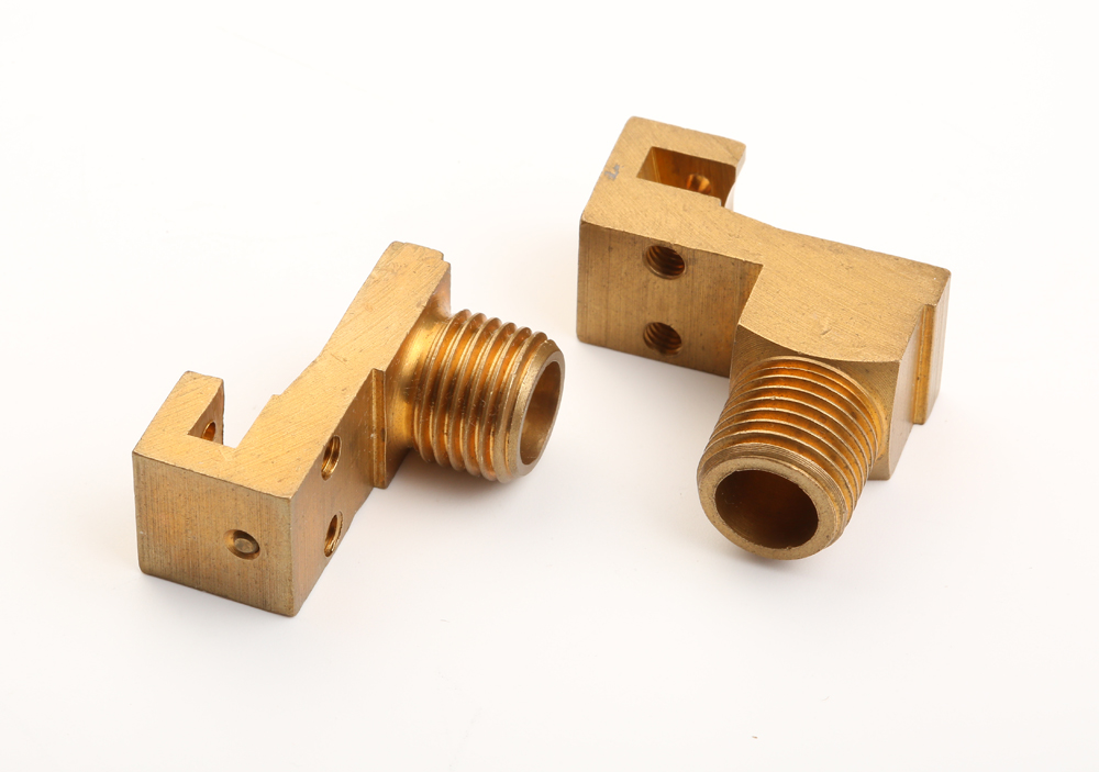
Le choix des matériaux constitue la base de la stabilité du processus. Il convient d’adapter la nuance de l’alliage de cuivre à la conductivité, à la résistance et à la difficulté d’usinage de la pièce — par exemple, le cuivre pur C101 pour les applications nécessitant une conductivité élevée, et le cuivre à usinage facile C14500 pour la production de précision à grand volume. Avant le lancement de la production à grande échelle, les équipes doivent vérifier les certificats des matériaux, les conditions de dureté et les stocks destinés à l’usinage. Cette étape permet d’éviter le mélange des matériaux et les performances inégales qui entraîneraient des rebuts, et elle réduit le gaspillage inutile de cuivre, matériau de grande valeur.
1.2 Analyse DFM et planification des processus
Avant le début de l'usinage, les ingénieurs procèdent à une analyse complète de la fabricabilité. Ils se concentrent sur la faisabilité de l'épaisseur des parois, les rayons des angles internes, les structures à cavités et alésages profonds, l'accumulation des tolérances et les exigences en matière d'état de surface. Sur la base de cette analyse, les équipes définissent les repères de serrage, les séquences d'usinage, les trajectoires d'outils de coupe et les stratégies multiaxiales. Des processus bien planifiés réduisent les changements de gabarits, limitent l’usure des outils et garantissent des résultats dimensionnels homogènes d’un lot de production à l’autre.
1.3 Mise en place du dispositif de fixation et serrage de la pièce
La relative tendreté du cuivre le rend sensible à la déformation par serrage lorsque la force est trop élevée, et aux vibrations de coupe lorsque la force est trop faible. C'est pourquoi il est nécessaire d'utiliser des dispositifs de serrage rigides et à répartition uniforme de la charge. Pour les pièces de haute précision, il est recommandé d'utiliser des mâchoires souples ou des dispositifs de serrage sur mesure afin de protéger les surfaces fonctionnelles, d'éviter les marques et les déformations, et de maintenir une précision de positionnement stable tout au long du cycle d'usinage.
1.4 Usinage de dégrossissage
L'ébauche vise avant tout un enlèvement de matière à haut rendement. Les opérateurs contrôlent la profondeur de coupe et l'engagement radial afin d'éviter toute déformation de la pièce due à la concentration de la chaleur de coupe. Le cuivre étant très ductile, l'évacuation des copeaux est une priorité absolue lors de l'ébauche. Les longs copeaux continus peuvent s'enrouler autour des outils et rayer les surfaces de la pièce. Des paramètres optimisés permettent également de limiter la formation de dépôts sur l'arête de coupe et de prolonger la durée de vie de l'outil.
1.5 Usinage de semi-finition et usinage de précision
Au cours de la semi-finition, les équipes réalisent les éléments principaux tels que les cavités, les rainures, les alésages et les filetages, en laissant une surépaisseur uniforme en vue de la finition finale. Cette étape nécessite une surveillance étroite de la formation de bavures, en particulier au niveau des arêtes des pièces et des sorties de trous. Une charge de coupe constante sur l'outil garantit un positionnement précis et une précision dimensionnelle sur l'ensemble des éléments.
1.6 Finition et contrôle de la qualité des surfaces
La finition détermine la tolérance finale et l'état de surface de la pièce. Cette étape fait appel à un engagement radial faible et à des vitesses d'avance optimisées afin de minimiser les marques d'outils et l'arrachement de matière. Des arêtes de coupe tranchantes et polies miroir sont essentielles pour l'usinage du cuivre, car elles empêchent l'entraînement de matière et la déformation. Un contrôle rigoureux de la surface est particulièrement important pour les contacts électriques et les composants d'interface thermique, où la planéité a un impact direct sur la fiabilité fonctionnelle.
1.7 Ébavurage et nettoyage
La grande ductilité du cuivre entraîne presque toujours la formation de bavures sur les arêtes après la découpe. En fonction des exigences de précision, les équipes ont recours à un ébavurage mécanique ou à une finition manuelle pour éliminer les bavures sans endommager les surfaces fonctionnelles. Après l'ébavurage, les pièces passent par plusieurs étapes de nettoyage afin d'éliminer les copeaux, les résidus de liquide de coupe et les contaminants, garantissant ainsi des performances de contact fiables dans les applications électriques et de gestion thermique.
1.8 Contrôle dimensionnel et validation de la qualité
Lors du contrôle final, les équipes procèdent à une vérification complète des cotes critiques, des tolérances géométriques (planéité, parallélisme, concentricité), de l'état de surface et de la qualité visuelle. L'usinage de précision standard du cuivre permet d'atteindre une précision dimensionnelle de ±0,01 mm. Les pièces ne sont validées pour l'emballage et la livraison qu'une fois que toutes les spécifications sont conformes aux exigences des plans.
2. Principaux défis techniques et causes profondes liés à l'usinage du cuivre
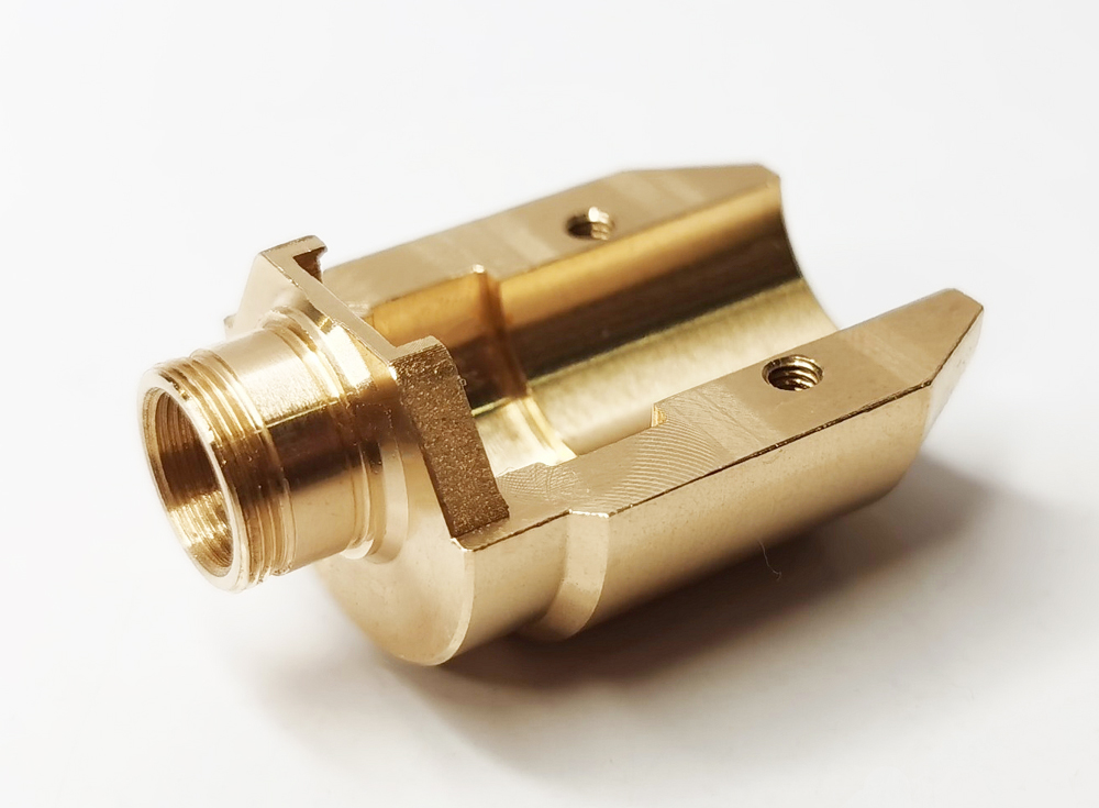
Bien que le cuivre semble, à première vue, tendre et facile à couper, ses propriétés physiques particulières posent de nombreux défis lors de son usinage. Il s'agit en réalité de l'un des métaux non ferreux les plus exigeants à usiner, nécessitant un contrôle rigoureux des processus.
2.1 Principales propriétés des matériaux ayant une incidence sur l'usinabilité
- Grande ductilité : Le cuivre pur présente une plasticité extrêmement élevée, ce qui rend difficile la rupture des copeaux lors de l'usinage, favorise la formation de longs copeaux continus et entraîne l'apparition de bavures par traînée sur les arêtes de coupe.
- Haute conductivité thermique : La chaleur générée par l'usinage se propage rapidement dans toute la pièce, ce qui peut entraîner une déformation dimensionnelle due à la chaleur et nuire à la stabilité des tolérances dans l'usinage de précision.
- Faible dureté : Les surfaces des pièces sont plus sensibles à la déformation due aux forces de serrage et de coupe, et les outils sont plus susceptibles de présenter des résidus de matière.
- Large plage de résistance à la traction : Les propriétés mécaniques varient considérablement d'un alliage de cuivre à l'autre : les forces de coupe du cuivre au béryllium peuvent être plusieurs fois supérieures à celles du cuivre pur.
2.2 Problèmes courants liés à l'usinage
- Bord renforcé (BUE) : Le cuivre mou adhère au tranchant, formant un dépôt qui altère la finition de surface et entraîne des variations dimensionnelles.
- Bavures excessives : Une ductilité élevée entraîne la formation importante de bavures sur les arêtes de coupe et aux sorties des trous, ce qui engendre des coûts supplémentaires liés aux opérations de débavurage secondaires.
- Usure par adhérence de l'outil : L'effet d'adhérence entre le cuivre et la surface de l'outil accélère l'usure des arêtes, ce qui réduit la durée de vie de l'outil et la stabilité du processus.
- Écart dû à la déformation thermique : La propagation rapide de la chaleur provoque une dilatation de la pièce à usiner pendant l'usinage ; après refroidissement, le retrait peut facilement faire sortir les cotes des tolérances.
3. Nuances courantes d'alliages de cuivre : usinabilité et guide de sélection
Les alliages de cuivre, dont la composition varie, présentent des différences considérables en termes d'usinabilité, de conductivité, de résistance mécanique et de coût. Le choix approprié consiste toujours à trouver le juste équilibre entre les exigences fonctionnelles et l'efficacité de la production.
| Catégorie de matériaux | Niveaux standard | Indice d'usinabilité | Niveau de force | Conductivité électrique | Applications typiques |
|---|---|---|---|---|---|
| Cuivre pur (cuivre rouge) | C101, C102, C110 | Modéré | Faible à moyen | Extrêmement élevé | Barres omnibus, connecteurs électriques, dissipateurs thermiques |
| Cuivre à usinage facile | C14500 | Haut | Moyen | Haut | Pièces tournées de précision, composants filetés, connecteurs |
| Laiton (alliage Cu-Zn) | C260, C360 | Très élevé | Moyen à élevé | Modéré | Vannes, raccords de tuyauterie, quincaillerie de construction |
| Bronze | C932, C954 | Bien | Haut | Modéré | Douilles de roulement, pièces d'usure, quincaillerie marine |
| Béryllium Cuivre | C17200 | Bien | Extrêmement élevé | Modéré | Composants aérospatiaux, ressorts à haute résistance, contacts à usage intensif |
Principe fondamental de sélection : Optez pour la gamme en cuivre pur lorsque la conductivité électrique est la priorité absolue. Optez pour le cuivre et le laiton faciles à usiner lorsque l'efficacité et le volume de production sont primordiaux. Optez pour le bronze et le cuivre au béryllium pour une résistance élevée à l'usure et des exigences de charge importantes.
4. Choix et optimisation des outils pour l'usinage du cuivre
L'outillage est au cœur du contrôle qualité de l'usinage du cuivre. Un mauvais choix d'outils entraîne rapidement la formation de dépôts sur les arêtes, des rayures en surface et une usure rapide des outils. L'optimisation porte sur trois aspects : le matériau de l'outil, les revêtements et la géométrie de coupe.
4.1 Choix des matériaux pour les outils
- Outils en carbure monobloc : Le choix idéal pour l'usinage de précision du cuivre, grâce à une rigidité élevée, une excellente résistance à l'usure, des vitesses de coupe plus élevées et une tenue de coupe supérieure. Les nuances de carbure polies réduisent considérablement l'adhérence de la matière.
- Outils en acier rapide (HSS) : Moins coûteux et adapté à l'usinage à faible vitesse et au prototypage en petites séries, mais avec une durée de vie des outils plus courte et une rentabilité moindre pour la production en série.
4.2 Revêtements d'outils et traitements de surface
Les revêtements durs standard, tels que le TiAlN, présentent une forte affinité avec le cuivre et peuvent en réalité nuire à l'adhérence. Pour l'usinage du cuivre, les meilleures options sont les suivantes : outils en carbure non revêtus, polis miroir ou des outils revêtus de DLC (carbone adamantin). Ces deux solutions réduisent le coefficient de frottement, limitent l'accumulation de matière et améliorent l'évacuation des copeaux.
4.3 Conception de la géométrie de coupe
Une géométrie d'outil adaptée est essentielle pour le contrôle des copeaux et la qualité de surface. Un angle de coupe positif important réduit les forces de coupe et la déformation du matériau tout en améliorant l'évacuation des copeaux. Un angle de dépouille plus large réduit le frottement sur les flancs et empêche les rayures en surface. Les arêtes de coupe polies miroir limitent l'accumulation de copeaux sur l'arête et offrent une meilleure finition lors des passes fines. La géométrie optimisée des goujures permet d'évacuer les longs copeaux de cuivre et d'éviter le colmatage.
5. Niveaux de précision et état de surface pour l'usinage CNC du cuivre
La capacité de tolérance dans l'usinage CNC du cuivre dépend de la rigidité de la machine, de l'état de l'outil, de la nuance du matériau et des paramètres du processus. Le tableau ci-dessous présente la précision et l'état de surface types pour différentes méthodes d'usinage :
| Procédé d'usinage | Tolérance standard | Tolérance de haute précision | Finition de surface Ra | Notes |
|---|---|---|---|---|
| Fraisage CNC | ±0,02 mm | ±0,01 mm | 0,8 – 1,6 μm | Cela dépend fortement de l'affûtage de l'outil et de la rigidité de la machine |
| Tournage CNC | ±0,02 mm | ±0,01 mm | 0,8 – 1,2 μm | Idéal pour les éléments concentriques en rotation |
| Fraisage de haute précision | ±0,01 mm | ±0,005 mm | 0,4 – 0,8 μm | Nécessite un environnement à température contrôlée et un contrôle stable du processus |
| Meulage (opération secondaire) | ±0,005 mm | ±0,002 mm | 0,2 – 0,4 μm | Utilisé pour les surfaces fonctionnelles critiques nécessitant une ultra-précision |
6. Règles d'optimisation DFM pour les pièces en cuivre
Le respect des principes de conception axée sur la fabricabilité permet de réduire efficacement le risque de déformation, d'améliorer l'efficacité de l'usinage et de renforcer la stabilité dimensionnelle des pièces en cuivre. Les principaux axes d'optimisation sont les suivants :
- Évitez les cavités étroites et profondes : Les cavités profondes et étroites limitent l'accès de l'outil et l'évacuation des copeaux, ce qui entraîne des vibrations et des problèmes de qualité de surface. Prévoyez un dégagement suffisant pour permettre le déplacement de l'outil et l'écoulement des copeaux.
- Respecter l'épaisseur minimale de la paroi : Le cuivre tendre est sensible aux déformations dues à la découpe et au serrage au niveau des sections à parois minces. Définissez une épaisseur de paroi raisonnable en fonction des dimensions de la pièce et évitez les conceptions à parois ultra-minces.
- Utilisez des angles intérieurs arrondis : Les angles internes vifs provoquent des variations brusques de la charge de coupe, ce qui entraîne l'apparition de marques de vibration et de bavures. Utilisez des rayons d'angle adaptés au rayon de l'outil.
- Assouplir les tolérances sur les surfaces non fonctionnelles : Évitez de définir des tolérances de précision inutilement strictes sur les faces non critiques, car cela augmenterait les coûts de production sans apporter de valeur ajoutée.
- Prévoir des surfaces de référence de serrage suffisantes : Concevez des surfaces de serrage planes et continues afin d'améliorer la rigidité et de réduire les erreurs de positionnement au cours des différentes opérations.
- Aligner les directions des éléments avec les directions d'usinage : Réduire au minimum l'usinage sur plusieurs faces et les réglages secondaires afin de limiter l'erreur de positionnement cumulée.
7. Stratégies clés pour l'optimisation des paramètres de découpe
Les paramètres d'usinage ont une incidence directe sur la qualité de surface, la durée de vie des outils et le rendement de production lors de l'usinage du cuivre. Ils doivent être ajustés de manière dynamique en fonction de la nuance du matériau et de l'étape d'usinage :
- Vitesse de rotation de la broche : Utilisez des vitesses de broche moyennes à élevées pour garantir un cisaillement net, sans étalement du matériau, et pour éviter la formation de bavures.
- Vitesse d'avance : Réglez l'avance à un niveau raisonnable : une avance trop lente entraîne une concentration de la chaleur de coupe, tandis qu'une avance trop rapide provoque l'apparition de bavures et des écarts dimensionnels.
- Profondeur de coupe : Trouvez le juste équilibre entre rendement et maîtrise des copeaux lors de l'ébauche ; optez pour un engagement radial léger lors de la finition afin de garantir la précision dimensionnelle et l'état de surface.
- Évacuation du liquide de refroidissement et des copeaux : Utilisez un arrosage abondant ou un jet d'air à haute pression pour évacuer rapidement la chaleur générée par l'usinage, briser les copeaux et éviter leur enchevêtrement ainsi que toute déformation thermique.
- Réglage spécifique au matériau : Utilisez des vitesses légèrement plus élevées pour les matériaux tendres comme le cuivre pur ; réduisez la vitesse et augmentez la rigidité de l'outil pour les alliages à haute résistance comme le cuivre-béryllium.
8. Principales applications industrielles de l'usinage CNC du cuivre
Le cuivre allie une excellente conductivité électrique, une excellente conductivité thermique et d'excellentes performances mécaniques. L'usinage CNC de précision permet d'exploiter pleinement le potentiel de ce matériau dans six grands secteurs industriels :
8.1 Composants électriques et électroniques
Le cuivre est le matériau de base des systèmes de transport d'énergie. Les barres omnibus, connecteurs, bornes et composants d'appareillage usinés par commande numérique garantissent une pression de contact précise et une faible résistance de contact. Cela permet d'éviter la surchauffe dans les systèmes à courant élevé et contribue à la fiabilité à long terme des installations électriques.
8.2 Systèmes de gestion thermique
Le cuivre conduit la chaleur bien mieux que l'aluminium, ce qui en fait le matériau de prédilection pour les applications de refroidissement haut de gamme. Les dissipateurs thermiques en cuivre usinés avec précision, les plaques de refroidissement à eau, les chambres à vapeur et les socles pour semi-conducteurs de puissance offrent une résistance thermique d'interface extrêmement faible, garantissant ainsi l'efficacité du refroidissement et la stabilité de la température des dispositifs à haute puissance.
8.3 Équipements automobiles et industriels
Le cuivre et les alliages de cuivre sont largement utilisés dans les modules électriques automobiles, les raccords hydrauliques, les ensembles de roulements et les pièces structurelles de précision. Ils conservent leur stabilité dimensionnelle et leur durabilité face aux vibrations, aux variations de température et aux contraintes mécaniques, ce qui les rend particulièrement adaptés aux environnements industriels difficiles.
8.4 Nouvelles énergies et systèmes de stockage d'énergie
Les onduleurs photovoltaïques, les éoliennes et les batteries de stockage d'énergie reposent en grande partie sur des composants conducteurs et thermiques en cuivre. La conductivité élevée et la résistance à la corrosion du cuivre garantissent un transfert d'énergie efficace et une longue durée de vie aux infrastructures dédiées aux énergies renouvelables.
8.5 Aérospatiale et défense
Les alliages de cuivre à haute résistance, tels que le cuivre au béryllium, sont utilisés pour la fabrication de connecteurs destinés à l'aérospatiale, de composants d'instruments de précision et de pièces de contact à haute fiabilité. Ils conservent des performances stables dans des conditions extrêmes de température, de vibrations et de corrosion, et répondent ainsi aux normes de fiabilité les plus strictes.
8.6 Télécommunications et infrastructures de données
Les connecteurs RF, les terminaux des stations de base de télécommunications et les systèmes de distribution électrique des centres de données reposent tous sur des pièces usinées de précision en cuivre. Un contrôle dimensionnel rigoureux garantit une transmission stable du signal, une faible perte de signal et un fonctionnement fiable des réseaux de communication.
9. Structure des coûts et facteurs déterminants
Le cuivre est un métal de grande valeur, et les coûts d'usinage dépendent de nombreux facteurs liés au matériau, au procédé et au volume. Les principaux facteurs de coût sont les suivants :
- Coût des matériaux : Les prix des matières premières varient considérablement selon la nuance de l'alliage ; les alliages spéciaux, tels que le cuivre au béryllium, coûtent nettement plus cher que le laiton standard.
- Complexité géométrique : La multiplication des caractéristiques et la complexité croissante des géométries entraînent une augmentation du temps d'usinage et des coûts de programmation. Les structures particulières, telles que les parois minces et les cavités profondes, font également grimper les taux de rebut.
- Exigences en matière de précision et de finition : Les tolérances serrées et les finitions de surface exigeantes nécessitent des opérations de finition et des contrôles supplémentaires, ainsi qu'une consommation d'outils plus importante.
- Volume de production : Les petits lots de prototypes entraînent des coûts de programmation, de mise en place et de réglage plus élevés par pièce ; la production en série réduit considérablement le coût unitaire.
- Opérations secondaires : Les traitements de surface, le meulage de précision et l'ébavurage spécial entraînent des coûts supplémentaires.
En optimisant la conception DFM, en uniformisant le choix des matériaux et en adoptant des solutions de processus adaptées, vous pouvez maîtriser efficacement les coûts globaux d'usinage du cuivre et améliorer la rentabilité de la production.
10. Principaux avantages de l'usinage CNC pour les pièces en cuivre
Les composants en cuivre exigent une grande précision dimensionnelle et des performances fonctionnelles fiables. L'usinage CNC offre le meilleur compromis entre précision, efficacité et flexibilité, avec des avantages majeurs, notamment :
- Précision dimensionnelle élevée : Permet d'obtenir systématiquement des tolérances de l'ordre du micron pour des ajustements de précision dans les applications électriques et thermiques.
- Excellente homogénéité des lots : La production pilotée par des programmes CNC réduit au minimum les variations de qualité d'un lot à l'autre, ce qui en fait la solution idéale pour la production à grande échelle.
- Qualité de surface supérieure : Des processus optimisés permettent d'obtenir directement des finitions de surface impeccables, ce qui réduit les opérations de polissage secondaires.
- Rendement élevé des matériaux : Une planification précise des trajectoires d'usinage permet de réduire les chutes de cuivre, un matériau de grande valeur, et de diminuer les coûts liés aux matières premières.
- Prise en charge des géométries complexes : Permet l'usinage simultané sur plusieurs axes pour la fabrication d'une seule pièce comportant des cavités complexes et des formes irrégulières.
- Adaptabilité de la production : Cette solution convient aussi bien aux prototypes à l'unité qu'aux essais en petites séries et à la production en volumes moyens, avec des délais de livraison maîtrisables.
11. Foire aux questions
Q1 : Les machines à commande numérique peuvent-elles découper du cuivre ?
Tout à fait. Les machines CNC équipées d’outils en carbure bien affûtés et de paramètres de coupe optimisés usinent le cuivre avec une grande efficacité. Le cuivre étant très ductile, l’usinage se concentre principalement sur le contrôle précis des copeaux et la prévention de l’adhérence. Dans des conditions de processus stables, il est possible d’atteindre une précision d’usinage de ±0,01 mm. Une vitesse de broche adaptée et une application adéquate du liquide de refroidissement sont essentielles pour éviter l'accumulation de copeaux sur l'arête de coupe et l'adhérence de l'outil.
Q2 : Quels sont les meilleurs matériaux pour l'usinage CNC : le laiton ou le cuivre pur ?
En termes d'usinabilité, le laiton offre de bien meilleures performances que le cuivre pur. Les laitons à usinage facile, tels que le C360, s'usinent 2 à 3 fois plus vite que le cuivre pur, tout en offrant une durée de vie des outils plus longue et en générant moins de bavures. Cela dit, le cuivre pur offre une conductivité électrique et thermique nettement supérieure. Le choix dépend toujours des priorités : optez pour le laiton si vous privilégiez l'efficacité, et pour le cuivre pur si vous privilégiez les performances fonctionnelles.
Q3 : Qu'est-ce que l'usinage CNC du cuivre ?
L'usinage CNC du cuivre fait appel à des machines-outils à commande numérique pour réaliser des opérations de fraisage, de tournage, de perçage et de taraudage sur du cuivre et des alliages de cuivre, permettant ainsi de produire des composants en cuivre de haute précision. Grâce à un outillage et à des paramètres optimisés, ce procédé garantit en permanence la précision dimensionnelle et la qualité de surface requises pour les pièces électriques et thermiques, et prend en charge l'ensemble du cycle de vie de la production, du prototype à la fabrication en série.
Q4 : Quelles sont les nuances de cuivre couramment utilisées dans l'usinage ?
Les nuances industrielles les plus couramment utilisées comprennent le cuivre pur C101 et C110, le cuivre à usinage facile C14500, le laiton C360, le bronze C932 et le cuivre au béryllium C17200. Le cuivre pur offre la meilleure conductivité électrique ; le cuivre à usinage facile et le laiton garantissent une efficacité de production optimale ; le bronze et le cuivre au béryllium offrent la résistance mécanique et la résistance à l'usure les plus élevées. Le choix doit toujours trouver un équilibre entre les exigences fonctionnelles et le coût d'usinage.
Conclusion
L'usinage CNC du cuivre constitue un défi technique complexe qui fait intervenir à la fois les propriétés du matériau, les solutions d'outillage et le contrôle des processus. Le choix judicieux du matériau et la conception adéquate du processus permettent d'atteindre un équilibre optimal entre précision, efficacité et coût.
PartsMastery est spécialisée dans les services d'usinage CNC de précision pour tous les types de cuivre et d'alliages de cuivre, couvrant l'ensemble du cycle de production, du développement de prototypes à la fabrication en série. En fonction des exigences fonctionnelles de vos pièces, nous proposons des solutions sur mesure tout-en-un, allant du choix des matériaux à l'optimisation des processus, garantissant ainsi la précision dimensionnelle, les performances fonctionnelles et la fiabilité des livraisons pour chaque composant.