






La industria aeroespacial es un sector clave de la fabricación de alta gama, con requisitos extremadamente estrictos en cuanto a la precisión dimensional de los componentes, el rendimiento de los materiales, la fiabilidad estructural y la uniformidad de los lotes.
Las piezas estructurales rotativas constituyen una gran parte de todos los componentes de los motores aeronáuticos, los sistemas de transmisión, los trenes de aterrizaje, los sistemas hidráulicos y de combustible, y los dispositivos de control de precisión de las naves espaciales.
Estas piezas deben funcionar de forma estable durante largos periodos de tiempo en condiciones adversas, como altas temperaturas, alta presión, rotación a alta velocidad y vibraciones intensas. Por ello, los requisitos que deben cumplir en cuanto a tolerancias geométricas, calidad de la superficie e integridad del material son mucho más exigentes que los de los productos industriales habituales.
El torneado CNC permite un control preciso de las trayectorias de la herramienta mediante sistemas de control digital. Permite realizar torneado exterior, mandrinado interior, refrentado, ranurado, roscado y mecanizado de contornos rotativos complejos en una sola configuración, lo que lo convierte en un proceso de fabricación fundamental para piezas aeronáuticas rotativas de precisión.
En comparación con los métodos de torneado tradicionales, el torneado CNC controla las trayectorias de mecanizado y los parámetros de corte mediante programas estandarizados. Reduce de forma eficaz las desviaciones dimensionales provocadas por la operación manual y garantiza una calidad constante en los distintos lotes de producción. Para los fabricantes del sector aeroespacial, esta capacidad de mecanizado estable constituye un apoyo técnico clave para el control de calidad, la mejora de la capacidad productiva y la producción en serie de alta precisión.
1. Principales escenarios de aplicación del torneado CNC en el sector aeroespacial
1.1 Componentes rotativos principales de los motores aeronáuticos
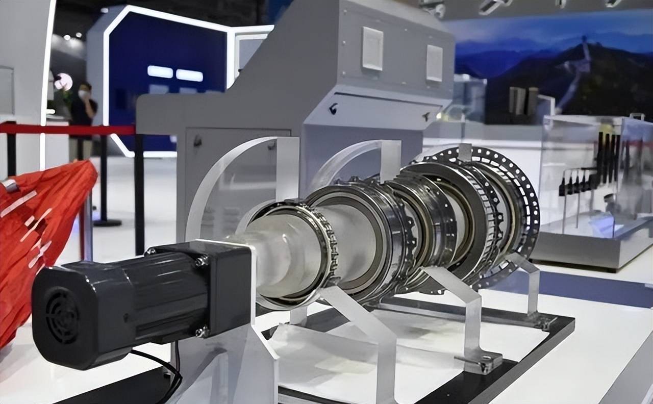
Como núcleo de potencia de las aeronaves, los motores aeronáuticos funcionan de forma continua en condiciones extremas de alta temperatura, alta presión y alta velocidad de rotación. La redondez, la concentricidad, la rugosidad superficial y la integridad del material de las piezas del motor determinan directamente la eficiencia operativa general y la vida útil. El torneado CNC es la solución de mecanizado más habitual para piezas rotativas, como ejes de motor, manguitos y anillos de unión.
En el caso de las piezas giratorias fundamentales —como los ejes de transmisión del motor, los ejes de soporte del rotor y los ejes de conexión de posicionamiento—, los fabricantes adoptan un plan de proceso por etapas que incluye el desbaste, el semiacabado y el acabado, con el fin de eliminar el material paso a paso y corregir la precisión geométrica. La fase de desbaste elimina la mayor parte del material de forma eficiente. El semiacabado corrige el contorno de la pieza y el punto de referencia de mecanizado. El acabado se centra en las dimensiones finales y la calidad de la superficie.
Los programas CNC estables garantizan la precisión posicional y las tolerancias geométricas de los diámetros de los ejes, los rebordes y las ranuras, cumpliendo así los requisitos de equilibrado dinámico para la rotación a alta velocidad.
En el caso de piezas como las camisas de cilindro del motor, los anillos de posicionamiento y los asientos de conexión de juntas, el torneado CNC permite realizar el mandrinado interior, el torneado exterior, el refrentado, el ranurado y el roscado en una sola sujeción. Esto reduce los errores de sujeción repetidos provocados por los traslados entre varias máquinas.
En el caso de las piezas de manguito de pared delgada, los fabricantes pueden reducir eficazmente la deformación provocada por el mecanizado optimizando los métodos de sujeción, controlando las cargas de corte y ajustando los márgenes de mecanizado. De este modo se garantiza la precisión dimensional de los diámetros interior y exterior, y se cumplen los estrictos requisitos de montaje de los motores aeronáuticos.
1.2 Componentes de transmisión de precisión
Los sistemas de transmisión aeroespaciales desempeñan funciones fundamentales de transmisión de potencia y control del movimiento. La precisión dimensional de los ejes de transmisión, los manguitos, las bridas de precisión y los anillos de posicionamiento influye directamente en la eficiencia de la transmisión y en la estabilidad de funcionamiento.
Estas piezas funcionan sometidas a cargas alternas de par y vibración durante largos periodos de tiempo, por lo que deben cumplir requisitos extremadamente exigentes en cuanto a concentricidad, circularidad y calidad de las superficies de contacto.
El torneado CNC establece un sistema de coordenadas de mecanizado preciso basado en el modelo 3D de la pieza. Controla la precisión posicional relativa de los diámetros exteriores, los orificios interiores, las caras frontales y las ranuras mediante movimientos programados de la herramienta. Los procesos de mecanizado estandarizados, las configuraciones de las herramientas y las normas de inspección garantizan la uniformidad dimensional de las piezas en la producción en serie.
La alta precisión geométrica reduce eficazmente las vibraciones debidas al desequilibrio durante el funcionamiento y mejora la eficiencia de la transmisión de potencia. Esto proporciona una base de fabricación sólida para el funcionamiento fiable a largo plazo de los sistemas de transmisión.
1.3 Componentes de precisión para sistemas hidráulicos y de combustible
Los sistemas hidráulicos, los sistemas de combustible y los dispositivos de control de fluidos de las aeronaves dependen de un gran número de válvulas de precisión, accesorios de tubería, manguitos de estanqueidad y elementos de posicionamiento para la transmisión de presión y el suministro de fluidos. Estas piezas suelen ser de tamaño reducido y presentan requisitos de alta precisión. Deben soportar altas presiones, vibraciones y la corrosión del fluido durante largos periodos de tiempo, por lo que se les exigen requisitos extremadamente estrictos en cuanto a estructuras de sellado, precisión de las roscas y calidad de las superficies de contacto.
El torneado CNC permite mecanizar con precisión roscas internas y externas, conos de sellado, ranuras de sellado, escalones de posicionamiento y orificios de precisión. El mecanizado multiproceso en una sola sujeción garantiza de forma eficaz la correlación dimensional de cada estructura de sellado.
En el caso de las piezas de conectores de alta presión, el mecanizado preciso de las roscas y las ranuras de sellado reduce el riesgo de fugas en las conexiones. Esto proporciona un apoyo fiable en la fabricación para las pruebas de rendimiento de sellado del sistema y garantiza un funcionamiento estable a largo plazo. En cuanto a los componentes de microprecisión, el uso de herramientas de microcorte adecuadas permite lograr un mecanizado de alta precisión en estructuras de tamaño minúsculo.
2. Adaptación del proceso de torneado para materiales aeroespaciales difíciles de mecanizar
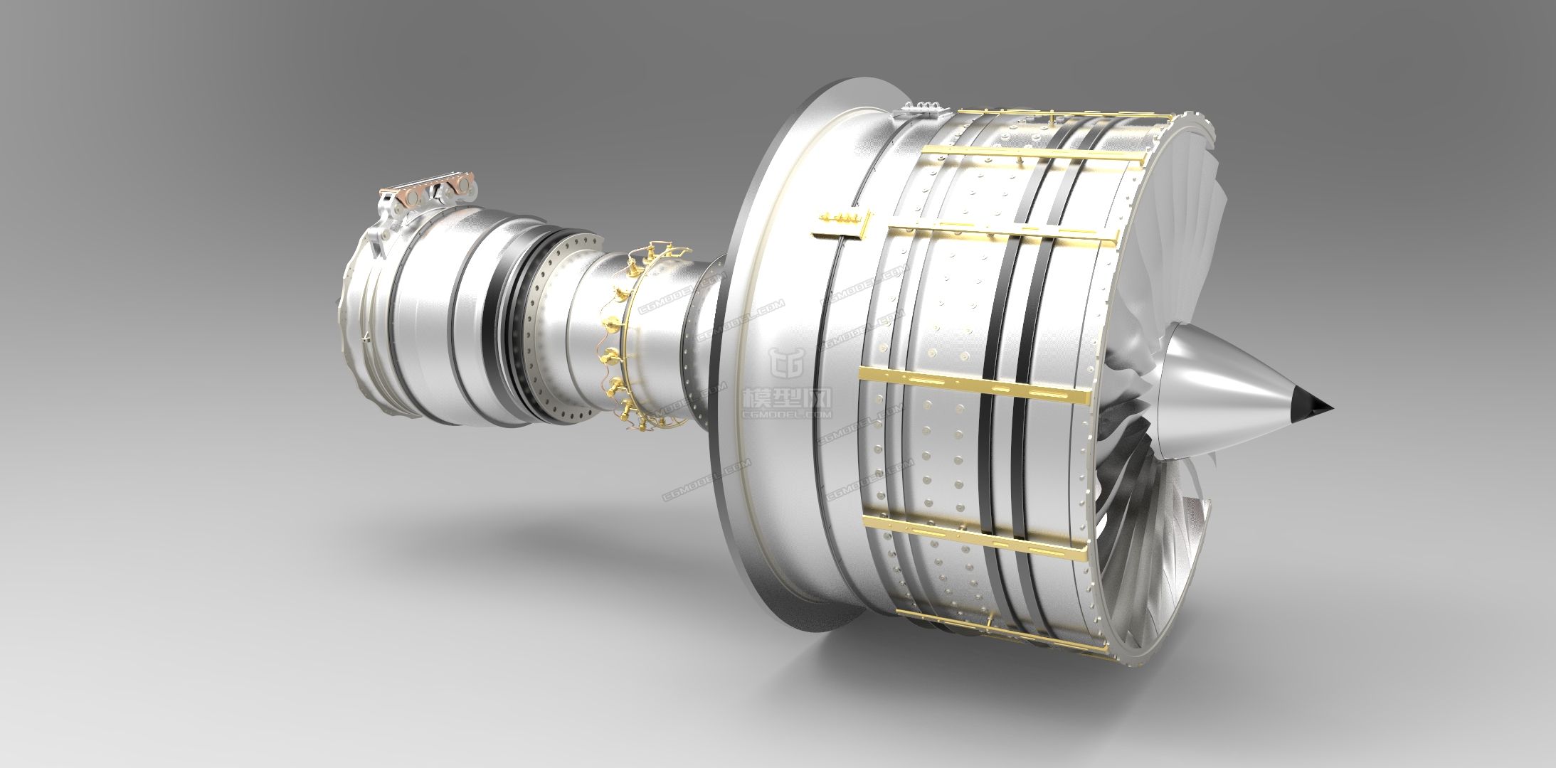
Para lograr ligereza, resistencia a las altas temperaturas y resistencia a la corrosión, en los productos aeroespaciales se utilizan ampliamente materiales de alto rendimiento, como las aleaciones de titanio, las superaleaciones a base de níquel y los aceros aleados de alta resistencia.
Estos materiales suelen presentar una mala mecanizabilidad, un endurecimiento por deformación evidente y una baja conductividad térmica, lo que plantea exigencias extremadamente elevadas a los procesos de mecanizado y a la rigidez de la máquina. El torneado CNC se adapta a las características de corte de los distintos materiales mediante el control digital de los parámetros, lo que permite un mecanizado estable y de alta precisión de materiales difíciles de mecanizar.
2.1 Mecanizado de componentes de aleación de titanio
Las aleaciones de titanio se utilizan ampliamente en piezas estructurales aeroespaciales y componentes de motores debido a su elevada relación resistencia-peso, su excelente resistencia a la corrosión y su buen comportamiento a altas temperaturas. Sin embargo, las aleaciones de titanio tienen una baja conductividad térmica, por lo que el calor generado durante el corte tiende a concentrarse en la zona del filo, lo que puede acelerar el desgaste de la herramienta. Además, el bajo módulo de elasticidad del material lo hace propenso a la deformación durante el mecanizado.
En el caso de las piezas de aleación de titanio, el torneado CNC permite controlar con precisión la velocidad de corte y la velocidad de avance. En combinación con un sistema de refrigeración a alta presión, disipa a tiempo el calor generado durante el corte y evita que la herramienta funcione durante mucho tiempo bajo una carga elevada.
La selección de materiales para herramientas y formas de filo adecuadas para el mecanizado de aleaciones de titanio, así como el mantenimiento de filos de corte afilados, pueden reducir eficazmente el desgaste anormal y garantizar la estabilidad dimensional de las piezas y la calidad del mecanizado superficial.
2.2 Mecanizado de componentes de superaleaciones a base de níquel
Las superaleaciones a base de níquel son el material principal de los componentes de la zona caliente de los motores aeronáuticos. Mantienen una alta resistencia mecánica y resistencia a la fluencia en entornos con temperaturas extremadamente elevadas. Sin embargo, estos materiales presentan una elevada resistencia al corte, un importante endurecimiento por deformación y un rápido desgaste de las herramientas, lo que se traduce en una gran dificultad de mecanizado.
En la planificación por etapas del torneado CNC, la fase de desbaste se centra en la eliminación eficiente de material, utilizando herramientas de alta resistencia para soportar grandes cargas de corte. La fase de acabado utiliza herramientas resistentes al desgaste y al calor, con parámetros de corte precisos, centrándose en garantizar la precisión dimensional y la integridad de la superficie.
Una distribución razonable de las tolerancias y la planificación de la trayectoria de la herramienta reducen la carga sobre la herramienta y mejoran la estabilidad del mecanizado, lo que permite cumplir los requisitos de mecanizado de alta precisión de las piezas de superaleaciones.
2.3 Mecanizado de componentes de aleación de aluminio de paredes delgadas
Las aleaciones de aluminio se utilizan ampliamente en piezas estructurales aeroespaciales y carcasas de equipos debido a su baja densidad, buena maquinabilidad y alta conductividad térmica. Sin embargo, las aleaciones de aluminio presentan una gran plasticidad, por lo que durante el mecanizado se generan fácilmente rebabas, lo que afecta a la calidad de la superficie. Las estructuras de paredes delgadas también presentan una rigidez insuficiente y son propensas a deformarse durante la sujeción y el corte.
Al mecanizar piezas de aleación de aluminio mediante torneado CNC, los fabricantes utilizan herramientas afiladas con ángulos de inclinación grandes y combinan velocidades de corte y avances razonables. Esto evita la formación de rebabas y reduce los arañazos en la superficie.
El diseño optimizado de evacuación de virutas evita que estas rayen dos veces la superficie mecanizada. En el caso de piezas de aleación de aluminio de paredes delgadas, los dispositivos de sujeción personalizados distribuyen la fuerza de sujeción, en combinación con parámetros de acabado de corte suave. Esto controla eficazmente la deformación durante el mecanizado y garantiza la precisión dimensional y geométrica de la pieza.
3. Métodos fundamentales de control de calidad para el mecanizado de alta precisión
3.1 Control de la precisión dimensional a lo largo de todo el proceso
Los requisitos de alta precisión de las piezas aeroespaciales se aplican a lo largo de todo el proceso de mecanizado. El establecimiento de un sistema de referencia y un sistema de coordenadas unificados para el mecanizado reduce los errores de posicionamiento causados por las repetidas sujeciones. Los programas CNC planifican trayectorias óptimas de la herramienta basándose en las características geométricas de la pieza y ajustan los parámetros de corte según las características del material, lo que reduce el riesgo de desviaciones dimensionales desde el origen.
La configuración por etapas del proceso —desbaste, semiakoado y acabado— asigna objetivos de mecanizado claros a cada fase. De este modo, se va acercando paso a paso a los requisitos dimensionales finales, al tiempo que se liberan las tensiones de mecanizado y se reduce el impacto de la deformación en la precisión.
Este modelo garantiza de forma fiable la redondez, la concentricidad, la precisión de las roscas y la rugosidad superficial de las piezas. Además, reduce los riesgos de tener que volver a trabajar las piezas y de generar desechos, y mejora la uniformidad de la producción en serie.
3.2 Inspección durante el proceso y compensación dinámica de herramientas
Durante la producción en serie, las herramientas se desgastan de forma natural a medida que avanza el mecanizado. Si no se ajustan a tiempo, las dimensiones de las piezas pueden variar gradualmente y superar el rango de tolerancia.
Los equipos de torneado CNC equipados con un sistema de inspección durante el proceso pueden recopilar datos dimensionales clave en tiempo real y evaluar automáticamente el estado de desgaste de las herramientas.
Cuando se detecta una tendencia de desviación dimensional, el sistema puede ajustar automáticamente la posición de mecanizado mediante la función de compensación de herramientas, corrigiendo las dimensiones de las piezas siguientes para que se mantengan dentro del margen de tolerancia. Este proceso no requiere la parada manual de la máquina para realizar mediciones. Reduce el error y el tiempo que supone la medición manual, y evita el riesgo de desviaciones dimensionales en el lote. Es especialmente adecuado para la producción en serie de piezas de precisión, como ejes y manguitos.
4. Mejoras en la capacidad de producción en serie y de fabricación digital
La fabricación aeroespacial requiere tanto una precisión extrema en el mecanizado como una eficiencia de producción estable y un sistema de calidad trazable. La integración del torneado CNC con la automatización y la tecnología digital permite satisfacer la doble exigencia de alta precisión y alta eficiencia, adaptándose a diferentes modos de producción, como la producción de gran variedad, en lotes pequeños y en serie, en el sector aeroespacial.
4.1 La producción automatizada aumenta la eficiencia de los equipos
Las unidades de torneado CNC equipadas con sistemas automáticos de carga y descarga y cambiadores automáticos de herramientas pueden llevar a cabo de forma automática todo el proceso de manipulación, sujeción, mecanizado y descarga de las piezas. Esto reduce el trabajo repetitivo de los operarios y evita los errores de posicionamiento provocados por la sujeción manual.
El modo de producción automatizado reduce considerablemente el tiempo auxiliar, aumenta el tiempo efectivo de funcionamiento de los equipos, estabiliza el ritmo de producción y garantiza los plazos de entrega de los pedidos. En el caso de piezas altamente estandarizadas, como conectores, manguitos y anillos de posicionamiento, las unidades de torneado automatizadas permiten una producción continua a largo plazo sin necesidad de supervisión, lo que mejora considerablemente la eficiencia de la fabricación.
4.2 La trazabilidad digital mejora la gestión de la calidad
La fabricación de componentes aeroespaciales requiere registros completos que permitan la trazabilidad de los procesos y la calidad. Los sistemas digitales de gestión de la producción pueden registrar de forma sincronizada los programas de mecanizado, los parámetros de los equipos, la información sobre las herramientas, los datos de inspección y los lotes de producción de cada lote de piezas, lo que permite una trazabilidad de la calidad a lo largo de todo el proceso.
Cuando se producen anomalías en la calidad, los datos trazables permiten localizar rápidamente el eslabón problemático y optimizar el plan de proceso de forma específica. Un sistema digital completo de control de calidad ayuda a las empresas a establecer procesos de producción estandarizados y a mejorar continuamente la uniformidad de los productos entre los distintos lotes, cumpliendo así los estrictos requisitos de control de calidad de la industria aeroespacial.
5. Tendencias del sector y perspectivas sobre el valor técnico
A medida que la industria aeroespacial sigue evolucionando hacia diseños ligeros, alto rendimiento, alta fiabilidad y fabricación inteligente, los requisitos para el mecanizado de precisión de componentes aumentan constantemente.
Como proceso fundamental para la fabricación de piezas giratorias, el torneado CNC abarca múltiples campos clave, entre los que se incluyen los motores aeronáuticos, los sistemas de transmisión y los sistemas hidráulicos de combustible. Es compatible con diversos materiales aeroespaciales, como las aleaciones de titanio, las superaleaciones y las aleaciones de aluminio, lo que lo convierte en una base técnica importante para la fabricación de precisión en el sector aeroespacial.
De cara al futuro, gracias a la mejora continua de los equipos de torneado multieje de alta precisión, la gestión inteligente de las herramientas, la inspección durante el proceso y los sistemas de producción digital, la precisión de mecanizado, la estabilidad y la eficiencia productiva del torneado CNC seguirán mejorando.
PartsMastery se centra en soluciones de mecanizado CNC de alto rendimiento. Ofrecemos asistencia técnica integral para todo el proceso, incluyendo la selección de herramientas, la optimización de procesos, el diseño de utillaje y la producción digital, de acuerdo con las características estructurales, las propiedades de los materiales y los requisitos de precisión de los componentes aeroespaciales. Ayudamos a los fabricantes aeroespaciales a mejorar la precisión en el mecanizado de piezas, la calidad del montaje y la fiabilidad operativa, y ofrecemos un apoyo fiable a la fabricación para el desarrollo de alta gama de la industria aeroespacial.