






In high-volume precision mechanical part manufacturing, you can never fully eliminate dimensional deviations — even with high-precision CNC equipment and standardized workflows. For general structural parts, minor deviations usually do not hurt real-world performance. In high-end sectors such as aerospace, medical devices, and precision automation, however, out-of-tolerance dimensions can directly cause assembly failures, reduce operating accuracy, and even weaken the long-term reliability of the entire system.
Fortunately, dimensional deviation is not an unfixable problem. The key is to accurately identify its root causes, pick the right correction method, and build a proactive prevention system. With systematic deviation analysis, targeted finish corrections, and smart process optimization, manufacturers can effectively raise part pass rates, cut rework costs, and keep dimensional consistency across all mass production runs.
1. Core Causes of Post-Machining Dimensional Deviation
Dimensional deviation rarely comes from a single problem. More often, it grows out of a mix of factors: equipment condition, material properties, and process design. For this reason, manufacturers must first find the root cause before applying any fix — this stops the same issue from happening again.
1.1 Machine and Tool Wear Over Time
The baseline accuracy of CNC equipment forms the foundation for consistent part dimensions. After long hours of nonstop operation, natural wear affects a machine’s internal drive parts. Over time, this wear shows up directly as drifting part dimensions:
- Wear on guideways, ball screws, and other drive parts reduces axis positioning and repeatability, creating systematic deviation
- Cutting edge wear after long machining hours causes tool deflection, pulling actual cut dimensions away from set values
- Uncalibrated machines with shifted axis references create one-directional over-tolerance across entire production batches
1.2 Material Deformation and Size Shift
Different materials have very different mechanical properties. If you skip custom process planning, these materials will almost always shift in size after machining:
- Cutting releases residual internal stress trapped in raw metal stock. This stress causes warping and deformation that push dimensions out of tolerance
- Low-rigidity structures such as thin walls, slender shafts, and deep cavities bend elastically under cutting force, creating tool deflection errors
- Cutting heat builds up during machining and makes workpieces expand. Once cooled and shrunk, final dimensions differ from in-process measurements
1.3 Poor Process Design and Mismatched Parameters
Poor process planning introduces dimensional errors right from the start. In fact, even top-tier equipment accuracy cannot guarantee good parts if your process design is flawed:
- Mismatched cutting speed, feed rate, and depth of cut amplify cutting vibration and tool deformation, and break dimensional stability
- Bad tool path planning, repeated engagement moves, and accumulated backlash gradually make dimensional errors worse
- Inconsistent positioning datums across multiple clamping setups create positioning errors, and directly harm the accuracy of critical dimensions
2. Three Correction Solutions for Post-Machining Dimensional Deviation
When you find dimensional deviation on a part, you do not have to scrap it right away. Instead, you can choose the right correction method based on deviation size, part structure, and performance needs. This approach cuts production costs while keeping part quality fully intact.
2.1 Secondary Finish Machining
This is the most widely used correction method, and it works best for oversized parts with enough leftover machining stock. You remove extra material with a light finishing pass to pull dimensions back into the allowed tolerance range:
- You can correct dimensions and geometric tolerances on mating surfaces (such as flat faces and outer diameters) using precision milling and grinding
- You can enlarge undersized bores with boring and reaming to maintain consistent roundness and coaxiality
- Before you start, remeasure actual dimensions carefully and check the remaining stock. Always use a single reference datum for the second clamping to avoid adding new positioning errors
As a rule, successful secondary finishing depends on tight control of cut depth and clamping accuracy. It only works for dimensions with enough leftover material; overcutting will ruin the part entirely.
2.2 Surface Coating for Size Compensation
When a part measures slightly under the lower tolerance limit and the gap is small, you can make up the difference with surface treatment. These processes add thin layers of material without any extra cutting work:
- Common options include electroplating, electroless plating, and hard anodizing. You can fine-tune coating thickness precisely by adjusting process parameters
- These processes do more than just fix dimensions. They also boost surface hardness, wear resistance, and corrosion resistance for better overall performance
- You must calculate coating thickness and tolerance headroom ahead of time to prevent oversize after coating. You also need to verify strong adhesion between the coating and base material
2.3 Assembly Tolerance Adjustment
For deviations on non-critical functional dimensions, you can absorb the error by tweaking assembly relationships. Best of all, you do not need to rework the actual part at all:
- Adjust tolerance bands of mating parts and use selective matching to keep overall assembly accuracy on target
- Tweak installation designs for auxiliary structures and leave adjustment room to soak up small dimensional deviations
- You must run full structural and performance checks before using this method. Never apply it to critical dimensions tied to safety or core moving fits
3. Proactive Prevention and Control System for Dimensional Deviation
All that said, preventing deviation at the source delivers far better cost savings than fixing parts after the fact. When you build an end-to-end precision control system, you drastically cut over-tolerance rates and keep mass production running steadily.
3.1 Upfront Process Planning and Risk Mapping
To start with, you should map out all risk points before machining and head off deviations at the process design stage:
- For flexible, easy-to-deform structures like thin walls and deep cavities, optimize clamping setups and add auxiliary supports to spread out cutting force
- Add stress relief steps for warp-prone materials, and only run finish machining after aging treatment releases internal stress from roughing
- Break work into clear roughing, semi-finishing, and finishing stages. This releases cutting stress gradually and lets you control stock for each step precisely
3.2 End-to-End Inspection and Closed-Loop Control
Additionally, you should weave inspection into every step of production. This lets you catch issues early, make fast adjustments, and avoid costly full-batch scrap:
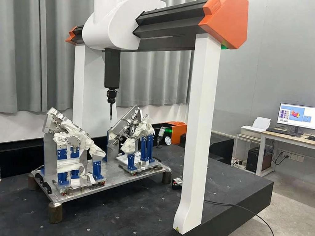
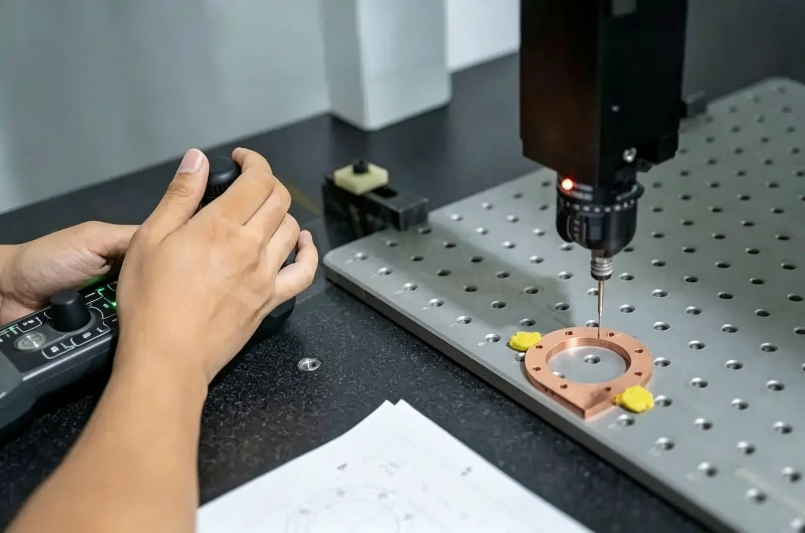
- Run full first-article dimensional checks with coordinate measuring machines, and only start mass production after you confirm all parameters are correct
- Add inspection checkpoints after key operations to track dimensional shifts in real time, and offset tool wear and thermal deformation as you go
- Set up a batch sampling routine to maintain dimensional consistency during mass production and stop systematic deviation from growing worse
3.3 Stable In-Process Control Practices
Finally, you can reduce process variables with standardized management to keep machining conditions consistent run after run:
- Build a tool life management system and replace tools on a set schedule to avoid deviation from excessive wear
- Run regular machine accuracy calibration and maintenance to keep baseline equipment performance within qualified limits
- Standardize cutting parameter libraries for different materials to reduce dimensional swings from manual parameter changes
4. How to Decide If a Part Needs Rework
Not every dimensional deviation needs a full correction. Unnecessary rework only adds extra cost for no real benefit. For each case, you should grade the issue based on tolerance rules and part function to pick the most cost-effective solution.
4.1 Judge by Tolerance Band Limits
Specifically, you should use the tolerance ranges on engineering drawings as your core reference for decision-making:
- Dimensions inside the tolerance band: accept the part as qualified, with no extra correction needed
- Slight over-tolerance with no impact on core functions: weigh repair cost and practicality, and prioritize low-cost fix options
- Severe over-tolerance with no fixable stock or risk to structural safety: scrap the part to prevent later assembly or performance failures
4.2 Prioritize by Part Function and Criticality
You should also adjust your approach based on how critical each dimension is to the final product:
- Critical mating surfaces, motion pairs, and safety-related dimensions must meet tolerance rules strictly. You must rework or scrap any part that fails these checks
- For non-critical cosmetic surfaces and auxiliary mounting features, you can approve a concession after design review, as long as they do not hurt overall equipment performance
Conclusion
Ultimately, dimensional deviation in machined parts comes from a mix of equipment, material, and process factors. After-the-fact fixes only work as a backup solution. Proactive process optimization and end-to-end quality control form the core strategy for consistent precision and lower rework rates.
PartsMastery focuses on precision machining services. With a proven process planning system and strict end-to-end quality control, we deliver custom high-precision part manufacturing solutions. We help customers keep dimensional deviations under control and ensure stable, high-quality results across all mass production orders.