






In CNC milling operations, climb milling and conventional milling represent two fundamental cutting strategies. Their differences extend far beyond the relative direction of tool rotation and workpiece feed — they directly determine cutting load characteristics, surface finish quality, tool wear rates, and machining system stability. Selecting the correct milling direction is a critical process decision that balances machining efficiency, manufacturing cost, and part precision. This article systematically breaks down the working principles of both milling methods, compares their performance across multiple dimensions, and provides a standardized selection strategy aligned with material types, process stages, and equipment conditions, serving as a practical reference for CNC process planning.
1. Core Cutting Mechanisms of the Two Milling Methods
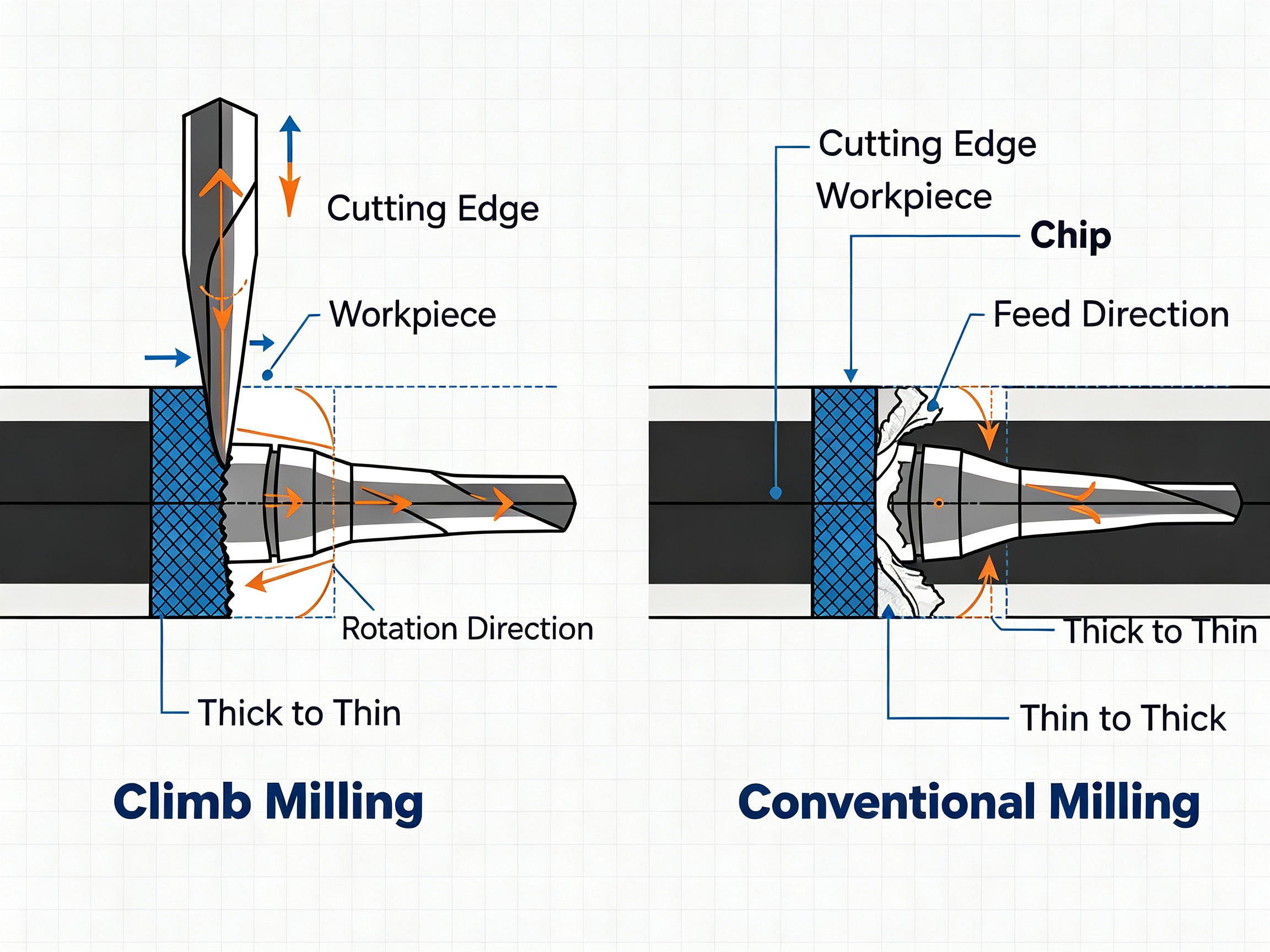
The essential distinction between milling directions lies in the relative motion of the cutting edge as it engages the workpiece, and the resulting chip thickness variation — this is the underlying source of all performance differences.
1.1 Climb Milling
Climb milling, also known as down milling, is defined by the tool rotating in the same direction as the workpiece feed. At the moment the cutting edge contacts the workpiece, chip thickness reaches its maximum value. As the tool rotates and advances, chip thickness gradually decreases, approaching zero as the edge exits the workpiece.
In this cutting mode, the cutting edge shears directly into the material without pre-friction between the edge and the workpiece surface. The vertical component of the cutting force presses the workpiece against the fixture base, creating a stable cutting state when clamping rigidity is sufficient.
1.2 Conventional Milling
Conventional milling, also referred to as up milling, features the tool rotating in the opposite direction to the workpiece feed. When the cutting edge first makes contact with the workpiece, chip thickness is nearly zero. The edge first undergoes extrusion and friction on the workpiece surface, then gradually penetrates the material as feed advances, with chip thickness increasing continuously to its maximum at the end of the cutting stroke.
This mode delivers smoother cutting edge engagement with lower impact loads, but the initial friction phase generates extra heat and edge wear. The component of the cutting force tends to lift the workpiece away from the fixture and push the worktable in the reverse feed direction.
2. Multi-Dimensional Performance Comparison
Based on their different cutting mechanisms, the two milling methods show significant divergence in core indicators such as cutting load, surface quality, and tool life. The detailed comparison is as follows:
2.1 Cutting Force and Machining Stability
- Climb milling: The vertical cutting force component presses downward on the workpiece, improving cutting rigidity. However, the horizontal force component aligns with the feed direction. If backlash exists in the machine tool’s lead screw, it can cause sudden worktable displacement, chatter, overcutting, or even tool breakage.
- Conventional milling: The horizontal cutting force component acts opposite to the feed direction, offsetting displacement risks caused by transmission backlash. It delivers stronger cutting stability on older equipment. However, the vertical force component lifts upward, placing higher demands on clamping force.
2.2 Heat Transfer and Chip Evacuation
In climb milling, chips form from thick to thin, and cutting heat dissipates rapidly from the cutting zone along with the chips. Over 70% of generated heat is carried away by the chips, resulting in low heat accumulation in both the workpiece and tool, and low risk of thermal deformation.
In conventional milling, the cutting edge experiences friction before cutting, leading to concentrated heat in the contact area. Slow chip formation allows more heat to conduct into the workpiece and tool substrate, increasing the risk of work hardening and dimensional thermal deviation.
2.3 Surface Quality and Dimensional Accuracy
Climb milling produces clean material shear separation without pre-friction extrusion, resulting in low residual surface stress and uniform tool marks. It can achieve finished surfaces with Ra ≤ 0.8μm and delivers excellent dimensional consistency, making it suitable for precision parts with tolerances within ±0.01mm.
Conventional milling, due to initial extrusion friction, tends to produce work-hardened layers and tear marks on the workpiece surface. Surface roughness typically exceeds Ra 1.6μm, with more edge burrs, often requiring subsequent deburring and polishing operations.
2.4 Tool Life Performance
Under equivalent cutting parameters and clamping conditions, climb milling causes lighter frictional wear on the cutting edge and lower thermal load, typically increasing tool life by 10% to 25% in mass production. However, when engaging workpieces with scale or oxide layers, the impact load at the moment of thick-chip entry can cause edge chipping.
The gradual edge engagement of conventional milling offers stronger impact resistance, making it suitable for roughing irregular blank surfaces. However, sustained frictional wear accelerates flank wear, with significantly higher tool wear rates when machining work-hardening materials such as stainless steel and titanium alloys.
Core Performance Indicator Comparison Table
| Comparison Dimension | Climb Milling | Conventional Milling |
|---|---|---|
| Chip thickness variation | Thick to thin; maximum thickness at cutting entry | Thin to thick; near-zero thickness at cutting entry |
| Cutting force direction | Vertical force presses workpiece downward; horizontal force aligns with feed direction | Vertical force lifts workpiece upward; horizontal force opposes feed direction |
| Surface roughness | Achieves Ra 0.4–0.8μm with minimal burrs | Typically above Ra 1.6μm with noticeable tool marks and burrs |
| Thermal impact | Heat dissipates quickly with chips; low workpiece thermal deformation | Heat accumulates easily; higher temperature rise in workpiece and tool |
| Tool life | 10%–25% improvement under stable conditions | Shorter life due to greater frictional wear |
| Machine requirements | Requires high-rigidity equipment with backlash compensation | Compatible with older machines and equipment with greater backlash |
| Suitable processes | Finishing, semi-finishing, high-speed milling | Roughing, blank opening, irregular billet machining |
3. Scene-Based Milling Method Selection Framework
Neither milling method is universally superior. Selection must be made comprehensively based on three core factors: material properties, processing stage, and equipment conditions. The standardized selection logic is outlined below.
3.1 Selection by Material Type
Different materials vary in hardness, ductility, thermal conductivity, and work-hardening tendency, which determine their compatibility with each cutting method. Refer to the following selection guide:
| Material Category | Typical Grades | Recommended Milling Method | Process Notes |
|---|---|---|---|
| Aluminum alloy | 6061, 7075, 2A12 | Climb milling preferred | Reduces tool adhesion and built-up edge, improves chip evacuation, lowers thermal deformation risk |
| Tool steel / medium carbon steel | P20, H13, 45 steel, S50C | Conventional for roughing, climb for finishing | Conventional milling handles blank scale and hard layers; climb milling ensures cavity precision and surface quality |
| Titanium alloy | Ti6Al4V, TC4 | Primarily climb milling | Pair with high-pressure coolant and low depth of cut to control cutting heat and reduce work hardening |
| Stainless steel | 304, 316L, 17-4PH | Conventional for roughing, climb for finishing | Conventional milling improves heavy-cut stability; climb milling controls edge burrs and surface tearing |
| Pure copper | C11000, T2 | Primarily conventional milling | Gentle cutting force reduces scratches and adhesion, avoiding surface defects from plastic deformation |
| Brass | H62, C3604 | Climb milling preferred | Compatible with high-speed cutting, delivers high-gloss surfaces, reduces subsequent polishing |
| Engineering plastics | POM, PA6, PTFE | Climb milling preferred | Reduces cutting heat, prevents material melting, burrs and thermal deformation |
| High-performance plastics | PEEK, PI, PETP | Primarily climb milling | Ensures dimensional accuracy and edge integrity, reduces material delamination and residual stress |
| Magnesium alloy | AZ31B, ZK60 | Primarily climb milling | Shortens cutting time and controls heat; fire safety controls must be implemented simultaneously |
| Carbon fiber composites | CFRP, carbon fiber sheet | Conventional milling + dedicated tools | Reduces fiber pull-out and edge delamination; pair with diamond-coated tools for improved quality |
3.2 Strategy by Processing Stage
Process priorities differ across stages, so the logic for selecting milling methods also varies:
- Roughing stage: The core goals are efficient material removal and tool safety. For blanks with oxide scale, cast/forged skin, or uneven stock, conventional milling is preferred to reduce impact load through gradual engagement. On high-rigidity CNC equipment with stable clamping, climb milling can also be used to achieve higher material removal rates.
- Semi-finishing stage: This stage balances stock removal and basic surface quality. Selection can be flexible based on equipment condition. Climb milling is preferred on rigid machines to leave uniform stock for finishing.
- Finishing stage: The core goals are surface precision and dimensional consistency. When equipment backlash is controllable, climb milling is the first choice. It effectively reduces tool marks, burrs, and subsequent grinding work, ensuring tight tolerance requirements.
3.3 Selection by Machine Tool Condition
Machine rigidity and transmission accuracy are the fundamental constraints for milling method selection:
- High-precision CNC machining centers: Equipped with ball screws, closed-loop servo control, and backlash compensation, these rigid machines are fully compatible with climb milling, unlocking its full advantages in efficiency, precision, and tool life.
- Older CNC machines / manual milling machines: With large transmission backlash and insufficient rigidity, climb milling easily causes tool chatter and overcutting. Conventional milling is preferred for roughing and semi-finishing to ensure safe and controllable machining.
4. Practical Tips for Milling Process Optimization
Milling performance depends not only on direction selection, but also on multi-dimensional optimization of parameters, clamping, and tooling. Below are key operational points.
4.1 Targeted Cutting Parameter Configuration
The two milling methods have different load characteristics and require matched cutting parameter ranges:
- Climb milling parameter recommendations: Use higher spindle speed, medium feed rate, and shallow cutting depth. Reference range for finishing: spindle speed 3000–8000 RPM, feed rate 600–1200 mm/min, axial depth of cut 0.3–1 mm, radial stepover 50%–70% of tool diameter, paired with sufficient coolant or minimum quantity lubrication (MQL).
- Conventional milling parameter recommendations: Use lower spindle speed, moderate feed, and deeper cutting depth. Reference range for roughing: spindle speed 2000–5000 RPM, feed rate 400–800 mm/min, axial depth of cut 1–2.5 mm, radial stepover 30%–50% of tool diameter, with continuous cooling to control frictional temperature rise.
All parameters must be verified through trial cutting according to actual machine power, tool coating, and workpiece clamping state. Confirm dimensional and surface quality before mass production.
4.2 Chatter and Machining Defect Prevention
Cutting chatter is a common issue in milling. It can be prevented and controlled through the following measures:
- Shorten tool overhang length and use rigid tool holders (such as hydraulic or shrink-fit holders) to reduce tool system deflection.
- Avoid the machine tool’s resonant speed range. When chatter occurs, adjust spindle speed first, then reduce depth of cut and feed rate.
- Use layered milling and stepped tool paths for deep cavities and thin-walled parts to reduce instantaneous cutting load.
- Optimize tool entry and exit paths, using arc engagement to avoid vertical impact of the cutting edge on the workpiece.
4.3 Clamping Rigidity and Backlash Management
- Fixture design must ensure sufficient positioning contact area and balanced clamping force. Soft materials require protective shims to avoid clamping damage, and cantilever parts need additional auxiliary support.
- Before applying climb milling, always verify machine tool backlash and compensate for transmission clearance via system parameters. If backlash cannot be effectively controlled on older equipment, avoid using climb milling for critical operations.
- Regularly recheck backlash values and positioning accuracy during mass production to prevent dimensional drift caused by equipment wear.
5. Typical Industry Applications
Different industries have distinct part characteristics and quality requirements, leading to differentiated milling process application patterns.
5.1 Aerospace Structural Component Machining
Aerospace titanium alloy and aluminum alloy thin-walled parts and frame structures have extremely high requirements for dimensional accuracy, surface integrity, and batch consistency. Climb milling is widely used in the finishing stage, paired with high-pressure internal cooling tools and optimized tool paths to reduce thin-wall deformation caused by cutting heat, while extending tool life and controlling processing loss of high-value materials. For roughing forged blanks, conventional milling can be used for opening to ensure process stability.
5.2 Precision Mold Cavity Machining
Precision molds such as injection molds and die-casting molds are processed in multiple stages. In the roughing stage, conventional milling is used for mold steel blanks to efficiently remove stock and handle surface hard layers. In semi-finishing and finishing stages, switch to climb milling to improve cavity surface finish, reduce manual polishing time, and ensure cavity contour geometric accuracy, shortening mold delivery cycles.
5.3 Medical Device Precision Component Machining
Orthopedic implants, surgical instruments, and precision medical housings impose strict requirements on surface finish, edge burrs, dimensional tolerances, and biocompatibility. For medical-grade materials such as titanium alloy, stainless steel, and PEEK, climb milling is used throughout the finishing stage. Paired with sharp dedicated tools and stable cutting parameters, it reduces surface defects and residual stress, meeting the high reliability standards of the medical industry.
6. Common Process Q&A
Q1: Is climb milling always better than conventional milling?
Not necessarily. The precision, efficiency, and tool life advantages of climb milling are built on the basis of sufficient machine rigidity and controllable backlash. In scenarios such as older equipment, blank roughing, and scaled workpieces, conventional milling offers better stability and fault tolerance. Blind use of climb milling will instead cause chatter, overcutting, and tool damage.
Q2: Which milling method should be chosen for hardened steel machining?
For roughing hardened steel (above HRC 50), conventional milling is recommended to reduce cutting edge impact load through gradual engagement and avoid edge chipping. For finishing, climb milling can be used on machines with sufficient rigidity, paired with high-hardness coated tools and small depth-of-cut parameters to achieve more stable surface quality.
Q3: What causes sudden worktable displacement during climb milling?
The core cause is excessive backlash in the machine tool’s transmission system, where the horizontal cutting force of climb milling drives instantaneous displacement of the worktable. Solutions include compensating for backlash via CNC system parameters, inspecting lead screw and guide rail wear, reducing cutting load, or temporarily switching to conventional milling.
Conclusion
Climb milling and conventional milling are fundamental process decisions in CNC milling. Neither is absolutely superior; the key is to match them according to material properties, processing stage, equipment condition, and quality targets. In modern CNC machining systems, climb milling has become the mainstream choice for finishing and mass production due to its advantages in precision, efficiency, and tool life. Meanwhile, conventional milling retains irreplaceable value in roughing, older equipment, and special material processing thanks to its high fault tolerance.
PartsMastery specializes in high-precision CNC machining services, covering full-process manufacturing of custom metal and plastic components including milling, turning, drilling, and precision surface finishing. Our engineering team provides professional process evaluation, fixture design, and parameter optimization solutions tailored to the material properties, tolerance requirements, and production scenarios of different projects. We ensure part quality while achieving efficient mass production, delivering reliable precision manufacturing solutions for customers across all industries.