



Surface Feet per Minute (SFM) serves as the foundational benchmark for cutting speed in CNC machining, and it directly shapes tool life, part surface quality, and overall production efficiency. Many common process issues — from premature tool wear and chatter to inconsistent dimensional accuracy — often trace back to improperly set cutting speeds. Unlike spindle speed (RPM), SFM provides a material-specific reference that stays consistent regardless of tool diameter, making it the reliable standard for tuning parameters across different setups.
At PartsMastery, our process engineering team applies standardized SFM-based calculation methods to optimize cutting parameters for every project. We match material properties, tool specifications, and machine capabilities to deliver stable, repeatable results for both prototype development and volume production runs.
1. What Is SFM, and How Does It Differ from RPM?
1.1 Core Definition of SFM
SFM stands for Surface Feet per Minute. It describes the tangential linear speed at which a cutting edge moves across the workpiece surface, measured in feet per minute. Put simply, it reflects how fast the cutting edge is working, not how fast the spindle is spinning.
This metric is universal for a given material and tool combination. For example, a recommended SFM for 6061 aluminum applies to both a 0.25” end mill and a 2” face mill — only the required spindle speed changes to maintain the same surface speed. This consistency makes SFM the most reliable starting point for process setup.
1.2 Key Differences Between SFM and RPM
RPM (Revolutions Per Minute) measures how many times the spindle rotates each minute. It is a machine input setting, not a material performance metric.
The core distinction is straightforward: SFM defines the target cutting condition, while RPM is the machine adjustment needed to reach that condition. When you switch to a larger diameter tool, you must lower RPM to keep SFM constant; for smaller tools, you raise RPM. Using the same RPM across different tool sizes produces drastically different cutting behavior and often leads to premature tool failure.
2. Core Calculation Formulas and Practical Examples
2.1 SFM and RPM Conversion Formulas
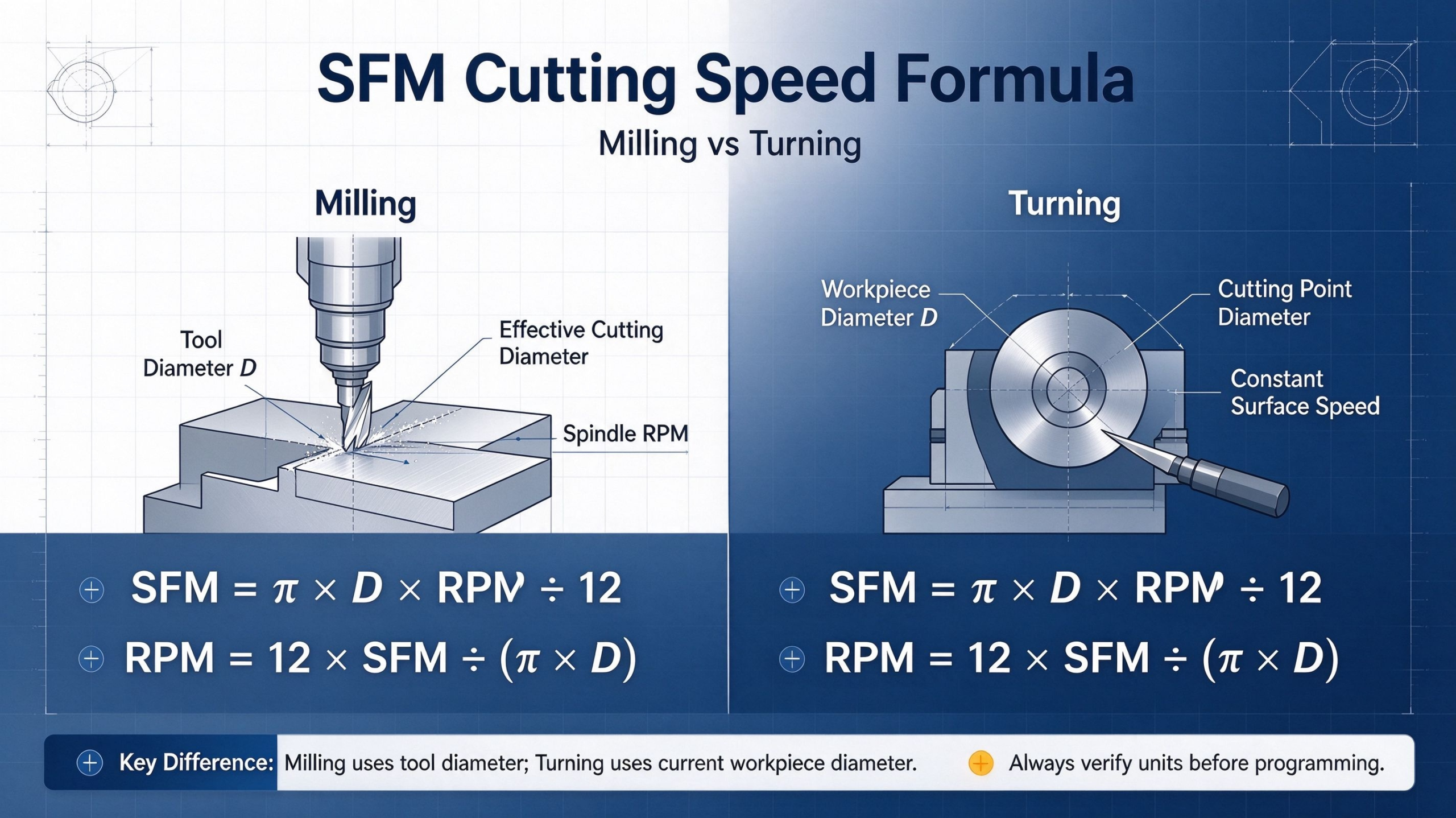
The standard imperial formulas link SFM, effective cutting diameter, and spindle speed:
- SFM = (π × D × RPM) ÷ 12
- RPM = (12 × SFM) ÷ (π × D)
Where D = effective cutting diameter in inches, π ≈ 3.1416, and 12 converts inches to feet.
For quick on-site calculation, the simplified RPM formula works reliably for most scenarios:
RPM ≈ (3.82 × SFM) ÷ D
2.2 Metric Unit Conversion
In metric manufacturing environments, cutting speed is typically expressed in meters per minute (m/min, or Vc). The conversion ratio is:
- 1 SFM = 0.3048 m/min
- 1 m/min ≈ 3.2808 SFM
Always verify unit consistency before entering values into a CNC program. Unit mismatches are one of the most common causes of incorrect spindle settings and unexpected tool damage.
2.3 Feed Rate Calculation
SFM sets the spindle speed, but you also need feed rate to complete the full parameter set. For milling operations:
Feed Rate (IPM) = RPM × Number of Effective Teeth × Chip Load per Tooth
Chip load defines how much material each cutting edge removes per revolution. Matching chip load to material and tool type is just as important as matching SFM. Running too light a chip load causes rubbing and excess heat, while too heavy a load chips or breaks cutting edges.
Calculation example: For a 0.75” 3-flute carbide end mill cutting 4140 steel at 300 SFM with a 0.002” chip load:
- Calculate RPM: RPM ≈ (3.82 × 300) ÷ 0.75 ≈ 1,528 RPM
- Calculate feed rate: Feed = 1,528 × 3 × 0.002 ≈ 9.2 IPM
Always cross-check calculated RPM against the maximum spindle speed rating of your machine before running the program.
3. Recommended SFM Ranges for Common Engineering Materials
SFM values always depend on tool material, coating, operation type (roughing vs. finishing), and coolant supply. The ranges below serve as starting points for solid carbide end mills in general peripheral milling. Final parameters must be validated based on specific tool data sheets and real-world cutting conditions.
| Workpiece Material | SFM Range (Carbide End Mill) | Key Process Notes |
|---|---|---|
| 6061 Aluminum | 600 – 1,200 | Use higher speeds for finishing; reduce for deep slotting. Polished flutes help prevent built-up edge |
| 1018 Mild Steel | 250 – 350 | Stable general-purpose range. Reduce speed for interrupted cuts and heavy roughing |
| 4140 Alloy Steel (Annealed) | 250 – 400 | Adjust based on hardness. Hardened grades require significantly lower SFM |
| 304 Stainless Steel | 100 – 300 | Prone to work hardening. Maintain consistent chip load and use adequate coolant |
| Ti-6Al-4V Titanium | 50 – 200 | Low thermal conductivity concentrates heat at the edge. Use rigid setups and high-pressure coolant |
| Gray Cast Iron | 100 – 400 | Abrasive material accelerates wear. Select appropriate tool grades for longer tool life |
4. SFM Application: Milling vs. Turning
4.1 SFM in CNC Milling
In milling operations, the rotating tool creates the cutting action. SFM is calculated using the effective cutting diameter of the tool. For standard end mills and face mills, this matches the nominal tool diameter. For ball nose mills, however, the effective diameter changes with axial depth of cut, so you must adjust RPM accordingly to maintain consistent surface speed.
Multi-face parts machined on 5-axis equipment also require careful SFM management across different tool engagement angles to avoid uneven tool wear and inconsistent surface finish.
4.2 SFM in CNC Turning
In turning operations, the workpiece rotates and the cutting tool remains stationary. SFM is calculated using the current workpiece diameter at the cutting point.
As you face a part from the outer diameter toward the center, cutting diameter shrinks. At constant RPM, surface speed drops as diameter decreases. For this reason, CNC lathes support Constant Surface Speed (CSS, often activated with G96 code), which automatically increases spindle speed as diameter shrinks. Always set a maximum spindle speed limit to prevent unsafe operating conditions at very small diameters.
5. Key Factors That Shape Optimal SFM Selection
There is no single “correct” SFM for a given material. You must adjust the baseline value based on five core factors:
5.1 Workpiece Material and Condition
Harder, less thermally conductive materials require lower cutting speeds. Annealed materials can run faster than hardened grades. Alloys prone to work hardening, such as stainless steel and titanium, also need carefully controlled SFM to avoid accelerated edge wear.
5.2 Tool Material and Coating
Carbide tools support significantly higher SFM than high-speed steel tools. Advanced coatings — such as TiN, TiCN, TiAlN, and diamond-like coatings — further raise heat resistance and wear limits. Always reference the tool manufacturer’s official data sheet for recommended cutting speeds, as generic charts only offer rough starting points.
5.3 Machine Rigidity and Fixturing
Even the best cutting parameters fail on a flexible setup. A rigid machine frame, short tool overhang, secure workholding, and stable fixturing let you run more aggressive SFM values without chatter. Weak setups require reduced speeds and feeds to avoid vibration and poor surface finish.
5.4 Operation Type and Engagement
Heavy slotting and full-width engagement generate more heat and tool load, so you must reduce SFM compared to light side finishing. Deep cuts and high radial engagement increase mechanical and thermal stress on the cutting edge, which calls for more conservative parameters.
5.5 Coolant and Chip Evacuation
Effective cooling and chip removal extend tool life and allow higher SFM. Through-tool coolant delivers the biggest benefit, especially for deep holes and deep cavities. Poor chip evacuation causes recutting and excess heat buildup, which forces you to run slower than the material would otherwise allow.
6. Common Mistakes and Troubleshooting
6.1 Frequent SFM Calculation Errors
- Mixing imperial and metric units: Always convert diameter to the correct unit before applying the formula.
- Using nominal instead of effective diameter: This is especially critical for ball nose tools, tapered tools, and angled cutting paths.
- Copying SFM values across different tool types: A value that works for a face mill will not necessarily work for a small drill or a thread mill.
- Ignoring spindle speed limits: Calculated RPM must never exceed the machine’s maximum safe spindle speed.
- Forgetting to recalculate feed rate after changing RPM: RPM changes directly affect chip load; always adjust feed rate accordingly.
6.2 Troubleshooting Common Process Issues
- Premature tool wear and overheating: Usually caused by SFM that is too high. Verify coolant delivery, reduce cutting speed, and confirm chip load is appropriate for the operation.
- Chatter and poor surface finish: Can stem from SFM that is too high or too low. First check rigidity, tool overhang, and fixturing, then fine-tune speed and feed in small increments.
- Built-up edge on the tool: Common in aluminum and ductile steels when SFM is too low or cutting edges are dull. Increase speed slightly, verify tool sharpness, and improve chip evacuation.
7. Practical Optimization Best Practices
To get the most value from SFM-based parameter setting, follow these three proven practices:
- Start with official tool manufacturer data: Generic charts are for reference only. Official tool data sheets account for substrate, coating, and geometry, and deliver far more reliable results.
- Validate and document every process: Run trial cuts, inspect tool wear, check surface finish, and record proven parameters. Over time, you build an internal database tailored to your machines and parts.
- Monitor tool condition during production: Track spindle load, surface quality, and dimensional drift to detect wear early. Adjust parameters or replace tools before they cause scrap or unplanned downtime.
Conclusion
SFM is far more than a simple calculation value — it is the core benchmark that ties together material properties, tool performance, and machine capability. Mastering the relationships between SFM, RPM, and feed rate helps manufacturing teams balance tool life, production speed, and part quality consistently.
At PartsMastery, we combine standardized SFM calculation methods with hands-on process validation to deliver precision CNC machining services. From prototype development to low-volume and mid-volume production, we optimize cutting parameters for every material, geometry, and tolerance requirement, helping customers achieve reliable, cost-effective manufacturing results.