






When a plastic part drawing lands on your desk, the first question engineers ask is rarely whether the geometry can be molded—it is whether the material will be easy to process. The answer lies in the material’s processing window: how much the process parameters can fluctuate before the part starts to show defects. A wide window tolerates temperature drift; a narrow window turns normal machine variation into extra trial rounds and schedule delays.
That is why having reliable temperature benchmarks at your fingertips is the first step in design review and process planning. Below is a consolidated reference of the most commonly used plastics and their recommended temperature ranges.
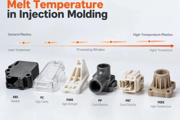
1. Melt Temperature Chart for Commodity Plastics
The “melt temperature” in the table below refers to the actual temperature of the molten plastic at the nozzle, not the setpoint displayed on the injection molding machine controller. These two values differ for physical reasons explained later in this article.
A processing window is a system-level concept. Beyond temperature, it encompasses injection pressure, injection speed, holding time, and cooling phase. This table focuses solely on the temperature dimension to help you quickly gauge how forgiving a material will be.
| Material | Melt Temperature (°C) | Mold Temperature (°C) |
|---|---|---|
| ABS | 200–260 | 40–80 |
| HDPE | 200–280 | 20–60 |
| HIPS | 180–260 | 20–60 |
| PA6 (Nylon 6) | 230–280 | 60–100 |
| PA66 (Nylon 66) | 260–300 | 60–100 |
| PBT | 240–270 | 60–100 |
| PC | 280–320 | 80–120 |
| PC-ABS | 240–280 | 60–90 |
| PMMA (Acrylic) | 210–250 | 50–80 |
| POM (Acetal) | 190–230 | 60–120 |
| PP | 200–280 | 20–80 |
| TPE / TPU (Elastomers) | 180–230 | 20–50 |
2. High-Temperature Engineering Plastics
High-performance engineering polymers operate in an entirely different temperature league, and their processing windows are typically narrower. Take PEEK, for example: its melt temperature commonly exceeds 350°C, and the mold must also be maintained at elevated temperatures. Standard injection molding machines often cannot handle these requirements.
| Material | Melt Temperature (°C) | Mold Temperature (°C) |
|---|---|---|
| PPS (Polyphenylene Sulfide) | 300–340 | 120–160 |
| PEEK | 350–400 | 150–200 |
| LCP (Liquid Crystal Polymer) | 280–340 | 80–120 |
When using either table above, keep two important caveats in mind:
- These are typical published ranges for the material family. The resin supplier’s processing guide for your specific grade is the final authority—especially for filled and modified grades, where the window is often narrowed further.
- The range is a boundary, not a target. Where you operate within that range depends on wall thickness, flow length, and surface finish requirements.
If your material is not listed, use the closest material in the same family as a starting point for reference—but always confirm against the supplier’s technical data sheet. Never apply the values directly.
3. Melt Temperature vs. Mold Temperature: Two Distinct Controls
Every table has two temperature columns, and they serve completely different functions. They are not interchangeable.
What does melt temperature control? It determines the viscosity of the molten polymer, which directly affects whether the plastic can fill thin walls and fine details before solidifying. Too high a viscosity causes short shots and flow marks; too low a viscosity can lead to flash and material degradation.
What does mold temperature control? It governs the cooling rate, which in turn influences surface gloss, internal residual stress, and dimensional stability. Higher mold temperatures improve surface quality but lengthen cycle time; lower mold temperatures speed up production but increase internal stress.
Where is each one set? Melt temperature is achieved through barrel zone heating, screw rotation speed, and back pressure. Mold temperature is controlled by a mold temperature controller and the cooling/heating circuits inside the mold.
The most common mistake on the production floor is treating mold temperature as if it were melt temperature—and then wondering why the numbers seem so low. The two parameters constrain each other but cannot substitute for one another. When reading the chart, both columns matter. However, from a material selection standpoint, melt temperature is the primary concern: lower melt temperature means shorter cooling time and less risk of material degradation; higher melt temperature means better flow in thin sections. It is a trade-off, not a default setting.
4. Three Temperature Values, Three Different Questions
For the same plastic, you may encounter three different temperature values in different places. They do not contradict each other—they simply answer different questions.
| Temperature Type | What It Means | What It Is Used For |
|---|---|---|
| Melting Point (listed in TDS) | The critical temperature at which the substance transitions from solid to a flowable state | Understanding the material’s intrinsic thermal properties; not a processing temperature |
| Melt Temperature (values in the chart above) | The actual temperature of the molten polymer at the nozzle | Assessing process feasibility and processing window width |
| Machine Setpoint (reading on the shop floor panel) | The temperature the controller sets based on heater bands and screw parameters | Matching with mold maker and machine operation; cannot replace the supplier’s guide |
Why is there a gap between the second and third rows? The physical reason is that most of the energy required to melt plastic comes from shear heat generated by screw rotation and back pressure—not from the heater bands. As a result, the setpoint displayed on the panel and the actual melt temperature are related but not equal.
In simple terms: melt temperature tells you whether the process route is correct; the machine reading tells you whether the equipment is running as expected. When the two diverge, it usually means the machine is executing its settings precisely, but the actual melt state has already drifted from the target.
5. What Shifts Your Actual Processing Window
The tables above describe the material family, but your drawing specifies a particular grade. Between the family and the grade lie several layers of modification, each of which can shift the window.
- Glass fiber or mineral fillers: Typically push the melt temperature higher, and the mold temperature usually needs to rise as well.
- Flame retardants, impact modifiers, UV stabilizers, and other additives: Shift both melt and mold temperature ranges; the direction depends on the specific additive system.
- Same material, different supplier: Even if the material name on the box is identical, different manufacturers use different grade formulations, resulting in different processing windows.
This does not mean the chart lacks value. It means the chart cannot identify your specific grade. The most cost-effective approach is to consult the processing guide in the grade’s Technical Data Sheet (TDS) before cutting the mold—not to troubleshoot repeatedly after the machine is already running.
6. Common Material Substitutions: How the Windows Differ
Materials that look similar are often not directly interchangeable. The following pairs are the most commonly encountered substitution combinations in design reviews.
| Material Comparison | Which Is More Forgiving | Key Differences |
|---|---|---|
| PA6 vs. PA66 | PA6 | PA66 requires higher processing temperatures and stricter drying conditions; the same mold will behave differently |
| PP vs. HDPE | HDPE | Both have wide ranges, but PP is more sensitive near the upper end of its temperature window |
| PC vs. PC-ABS | PC-ABS | PC requires higher temperatures with a narrower window and is more sensitive to residence time in the barrel |
| ABS vs. HIPS | HIPS | HIPS can be processed at lower temperatures with greater tolerance; ABS is hygroscopic and tends to discolor near its upper temperature limit |
The two nylon grades are the most frequently confused because their application scenarios overlap heavily. However, PA66 demands higher processing temperatures and more rigorous drying, so process parameters must be reconfirmed when substituting. ABS and HIPS are another common swap pair: ABS operates in a higher, narrower temperature range, while HIPS can use a significantly cooler window for the same part geometry.
Remember: belonging to the same material family does not mean sharing the same processing window. After changing materials, the cost of reconfirming the parameter range is far lower than the cost of repeated trial-and-error on the machine.
7. When the Chart Is Not Enough: Special Geometries
Everything discussed so far assumes conventional part geometry. The following three situations further narrow the usable temperature range and change where you can actually operate within the window.
1. Thin-wall, long-flow-path parts. Only the upper portion of the temperature range is usable, because the melt must remain fluid enough to fill the entire cavity before freezing. Mold flow analysis software can help predict whether the selected grade and process settings are capable of completing the fill before solidification.
2. Appearance and optical parts. Mold temperature and surface quality requirements squeeze the processing window from both sides. At this point, melt temperature alone no longer provides sufficient information; you need to consider the interplay of mold temperature, cooling rate, and melt temperature together.
3. Parts requiring certification or secondary operations. The range of acceptable grades is already narrowed from the outset, and the entire processing window needs to be reconfirmed based on the grade you ultimately select.
In these cases, the cost of verifying the window size through drawing and grade comparison before mold cutting is far lower than discovering the problem during the first trial run. The engineering team at PartsMastery recommends conducting a joint review of material selection, wall thickness, and flow length before mold machining begins.
8. Practical Q&A
What happens if the melt temperature is too low?
The melt viscosity becomes too high to reach the end of the flow path. Symptoms include short shots, visible flow marks, weak weld lines, and under-filled thin sections. When this occurs, gradually increasing the temperature while observing the fill pattern is usually more effective than simply raising injection pressure.
What happens if the melt temperature is too high?
Viscosity continues to drop, which helps filling, but it also begins to damage the polymer molecular chains. Common signs include discoloration and streaks from material degradation, as well as reduced impact strength—the latter often only surfaces during part testing. Additionally, higher temperatures extend cooling time, so the molding cycle increases accordingly.
Should all barrel zones be set to the same temperature?
Generally, no. The rear zone runs cooler to prevent premature melting in the feed section, while the front zone approaches the target melt temperature. What truly matters is the actual temperature at the nozzle—the value that corresponds to the supplier’s temperature range.
Can the material be changed after T1 samples are approved?
Changing the grade after T1 typically means another round of mold trials. Mold temperature, cooling time, and gate freeze time all shift with the material, so the approved sample no longer represents the final production part. If the schedule allows, lock in the grade before T1. If material selection is still undecided at that point, you can submit your drawings to PartsMastery, and we will help evaluate whether your candidate materials meet the part requirements.
Conclusion
A material’s processing window determines how much process variation a project can absorb, and that variation ultimately shows up in trial rounds and delivery timelines. If your selected grade sits near a boundary in the chart, or if your part features thin walls, long flow paths, or high appearance requirements, be sure to confirm the material’s actual processing window before cutting the mold.
For any questions about material selection or process evaluation, feel free to contact PartsMastery anytime. Our engineering team is ready to provide professional support.