Choosing between vacuum casting and 3D printing for plastic prototypes essentially comes down to answering three questions in sequence. First, can you actually manufacture the part? Second, can the result verify the current design goals? And third, does the overall cost make sense? Most comparison guides start directly with production volume, but this often puts the cart before the horse—because during the development stage when you have not yet frozen the design, volume itself remains an uncertain variable.
3D printing builds a part directly from a CAD file through layer-by-layer deposition, whereas vacuum casting requires an additional master pattern, a silicone mold, and finally polyurethane resin casting under vacuum. This core difference explains nearly every distinction between the two processes in terms of lead time, surface quality, material performance, design flexibility, and cost structure. This guide systematically analyzes the principles, applicable boundaries, verification capabilities, cost components, and selection logic of both processes, helping engineers choose the right process at the right time.
1. Selection Logic: Development Stage First, Process Second
Most comparison articles divide the applicable range of the two processes by production volume, but this approach only works after you completely freeze the design. In the actual development workflow, a more reasonable starting point is: what does this current round of plastic prototyping need to verify?
1.1 Four Verification Stages
Fit and assembly verification. Parts only need assembly checks for interference, and material performance is not yet critical. At this stage, 3D printing usually serves as the preferred choice because modification costs stay low and delivery runs fast.
Function and durability verification. Hinges, snap fits, seals, and repeatedly flexed parts require testing, so material performance begins to matter. At this stage, you should select the process and material according to the test type.
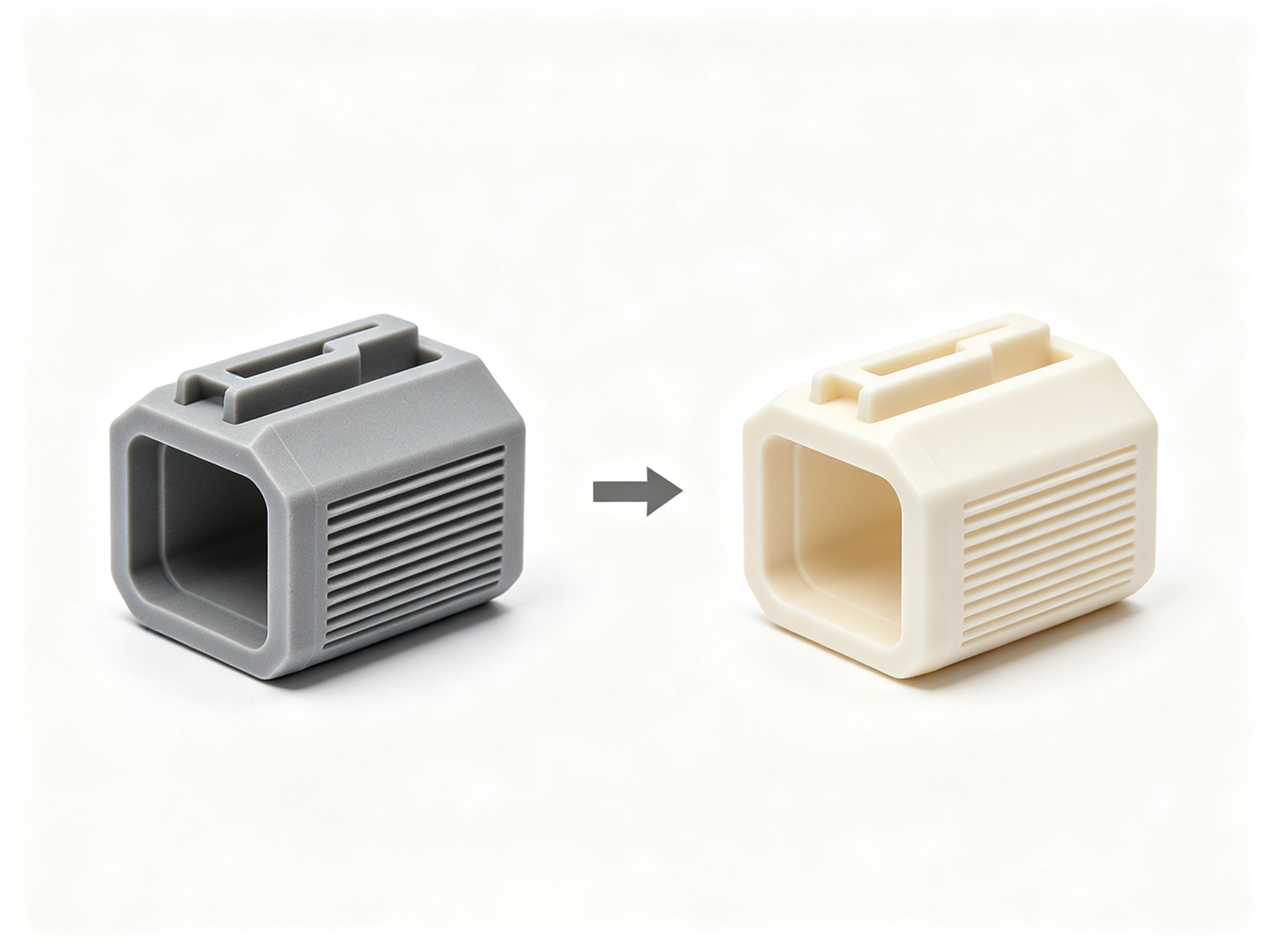
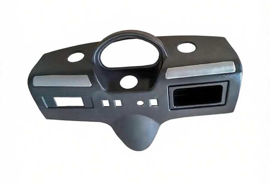
Appearance and display verification. Parts need to pass appearance evaluation by customers or users and must look like mass-produced products. At this stage, vacuum casting usually proves more suitable because surface quality and color come closer to injection-molded parts.
Pre-production preparation. Volume increases, and mold life plus the transition path to mass production become part of the decision. At this stage, evaluate whether to move from vacuum casting to aluminum or steel mold injection molding.
1.2 Why Stage Matters More Than Volume
The development stage determines what the prototype needs to verify, and the selected process must have the capability to verify that target. Skipping stage judgment and directly comparing prices often leads to using the wrong process to verify the wrong target. In contrast, identifying the stage first narrows down the viable processes and makes the subsequent comparison far more meaningful.
2. The Extra Step in Vacuum Casting: Master Pattern
3D printing goes from file to part in a single step, while vacuum casting adds a critical intermediate step: making a master pattern.
2.1 The Vacuum Casting Workflow
The vacuum casting workflow works as follows. First, you produce a physical master pattern matching the final product shape. Next, workers pour liquid silicone around the master pattern. After the silicone cures, workers cut it open and remove the master pattern, leaving a cavity that becomes the silicone mold. Workers then pour polyurethane resin into the silicone mold under vacuum, and after curing, they remove the part. Every cast part serves as a replica of the master pattern, so the surface quality and dimensional accuracy of the master pattern directly determine the upper limit of all cast parts.
2.2 Master Pattern Methods Compared
Manufacturers typically produce master patterns by 3D printing or CNC machining. A 3D printed master pattern offers speed and low cost, but the printing process limits its surface quality and dimensional accuracy. A CNC machined master pattern delivers tighter tolerances and a smoother surface, but it costs more and has a longer modification cycle.
Master Pattern Method
Advantages
Limitations
3D printed pattern
Fast production, fast modification, low cost
Surface and detail ceiling limited by printing process; layer lines replicate to every cast part
CNC machined pattern
High dimensional accuracy, smooth surface, tight tolerances
Higher pattern cost, longer lead time, higher design modification cost
2.3 Why Choosing Casting Means Two Decisions
Because the silicone mold precisely replicates the master pattern, it also replicates all of its defects. Layer lines, support marks, and unsanded surfaces will appear on every cast part, not just the first one. Therefore, choosing vacuum casting actually involves two decisions: choosing the casting process, and simultaneously choosing how you will make the master pattern.
PartsMastery covers this complete chain. We first produce the master pattern through CNC or 3D printing, then perform silicone mold fabrication and vacuum casting, ensuring consistent tolerance baselines and surface standards from pattern to cast part throughout the process. We return DFM (Design for Manufacturing) feedback with the quote, so we clearly identify any feature requiring inserts in the silicone mold before you make the master pattern.
2.4 Lead Time: First Part vs Whole Batch
The extra master pattern step also explains the difference in lead time. The first cast part arrives later than the first printed part because you must make the mold first. However, from the second part onward the situation reverses—casting reuses the same mold, while printing repeats the full build time for every unit. First-part lead time and whole-batch completion time represent two different numbers, and they may point to different processes. For a single prototype, 3D printing offers the more practical choice because you never get a chance to amortize the mold cost.
3. Manufacturing Boundaries of Each Process
The first step in selecting a process is not comparing prices, but determining whether you can manufacture the part at all.
3.1 3D Printing: No Mold, No Demolding Constraints
3D printing requires no mold, so you face no demolding constraints. You can print internal channels, lattice structures, and one-piece moving mechanisms all directly. However, the build envelope limits 3D printing, so you need to split and join oversized parts.
3.2 Vacuum Casting: Parting Line and Size Advantages
Vacuum casting requires opening a two-part silicone mold and removing the part, so it has parting line and release direction constraints. Manufacturers can still cast undercuts, deep cavities, and deep holes, but these features require additional inserts inside the mold, which increases mold cost and handling time and may affect consistency between parts. On the other hand, manufacturers can scale silicone molds to sizes far beyond most 3D printing build envelopes, so large simple parts may only allow vacuum casting as the viable option.
Part Feature
3D Printing
Vacuum Casting
Internal channels and lattice
Built in one piece, no constraints
Limited by parting line and release direction, usually impossible
Undercuts and deep cavities
No effect on build
Requires inserts or soluble cores
One-piece moving mechanisms
Completed in a single build
Usually requires splitting and assembly
Part size
Limited by build envelope
Mold size can exceed most build envelopes
If the design includes internal channels or moving features, 3D printing offers the simpler path. If the part is large and simple, vacuum casting may represent the only viable option.
4. What Prototypes Can and Cannot Verify
3D printing is not a single process. Instead, it constitutes a collection of processes including SLA, SLS, MJF, and FDM, each delivering different verification results.
4.1 Print Process Verification Capabilities
Print Process
What It Can Verify
Where It May Mislead
SLA stereolithography
Detail, surface, assembly checks
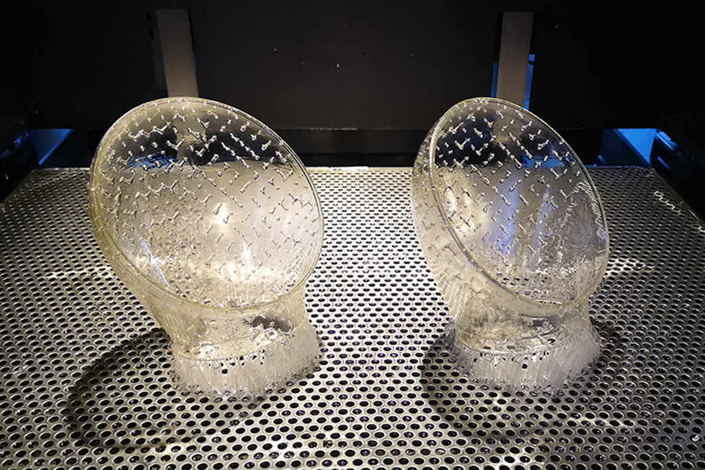
Resin is brittle and yellows under long-term UV exposure
SLS/MJF powder sintering
Structural strength, repeated flex testing
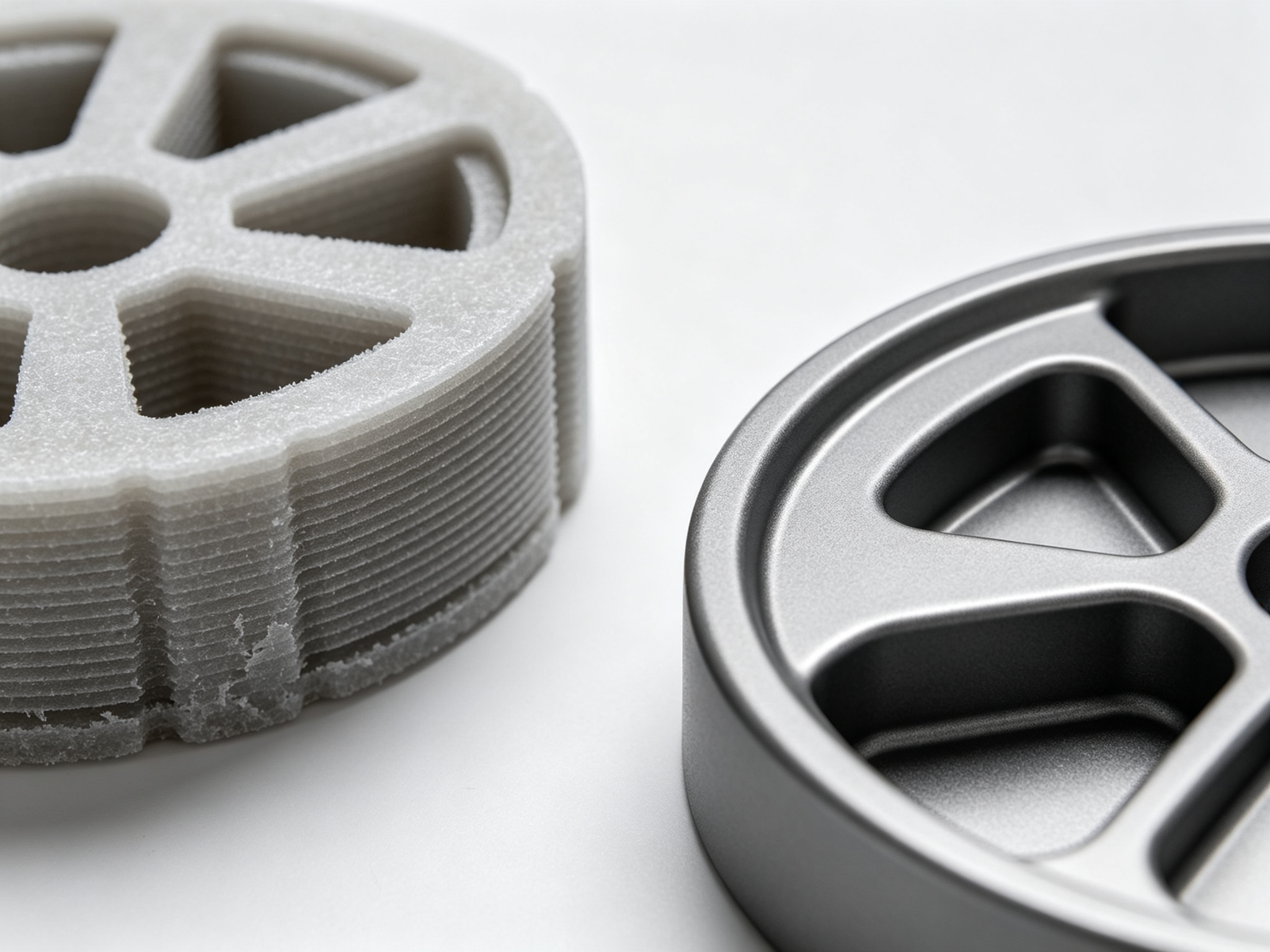
Grainy surface affects friction and appearance judgment
FDM fused deposition
Concept models, large simple shapes
Weak interlayer bonding; failures propagate along layer lines
4.2 Matching Process to Test Objective
Choosing which print process to use depends on the testing objective. Parts that flex repeatedly should use tough nylon materials (SLS/MJF) rather than brittle resin. Vacuum casting better suits parts requiring grip, drop, and appearance checks. PartsMastery offers the full range of 3D printing processes including SLA, SLS, MJF, and FDM, ensuring the print process matches the testing objective rather than the other way around.
4.3 What Cast Urethane Can Simulate
Vacuum cast polyurethane resins can simulate the room-temperature behavior and appearance of common engineering plastics, including ABS, PC, PP, and nylon-like grades. Soft rubber grades are also available with genuine Shore A hardness ratings. Transparent and flame-retardant grades are available as well.
4.4 The Boundaries of Prototype Verification
However, “simulation” has its boundaries. Cast polyurethane simulates how a material behaves and looks at room temperature, not how the material flows inside an injection mold. Therefore, cast parts can effectively verify assembly, grip, surface quality, and normal durability, but they cannot verify injection-related issues such as shrinkage, weld line locations, gate marks, or whether draft angles are sufficient for demolding. These constitute molding questions that neither printed nor cast parts can answer, and engineers typically leave them to the trial mold stage.
5. Cost Component Analysis
When production volume exceeds a few pieces, three cost components determine the comparison between the two processes.
5.1 Post-Processing Cost
3D printed parts typically require support removal, sanding, filling, priming, and painting before they achieve a presentable appearance. Vacuum cast parts come out of the mold with the surface already formed, so this significantly reduces post-processing workload. Workers can mix color into the resin before pouring, or custom color matching is available. For larger batches, we often recommend painting instead of bulk coloring because painting better maintains color consistency between parts.
One point worth clarifying early: you fix mold texture when you make the mold and cannot change it afterward. You determine both SPI polish grades and VDI textures at this stage, along with the post-processing and color plan for the entire batch. Changing the texture later means making a new mold.
5.2 Design Modification Cost
For 3D printing, a design modification means a new file and a new build, with nothing wasted. For vacuum casting, a design modification may require remaking the master pattern and refabricating the mold, so you pay for the same change twice. This leads to a practical rule: do not switch to vacuum casting while major dimensions are still changing, and do not stay on 3D printing once dimensions have stopped changing.
5.3 Mold Life Cost
Silicone molds are consumables, typically rated for a few dozen shots, and they do not fail suddenly. Surface quality declines first, followed by dimensional drift. This matters most for parts that must fit with other components: early and late parts from the same mold are not in the same condition. When the mold reaches the end of its life, you must make a new one. If the expected volume is much larger, you usually better invest this expense in a production steel mold.
6. Selection Decision Guide
Based on the above analysis, choosing between vacuum casting and 3D printing can follow this decision path step by step:
6.1 Four-Step Decision Path
Determine if you can manufacture the part. Internal channels or moving mechanisms → choose 3D printing. Oversized and simple part → choose vacuum casting. Both can manufacture → proceed to the next step.
Determine the development stage. Design still changing frequently, only 1-2 pieces needed → choose 3D printing. Design frozen, 5+ pieces needed with production-like appearance → choose vacuum casting.
Determine the verification objective. Only assembly checks needed → 3D printing suffices. Functional testing needed → select process and material according to test type. Customer appearance review needed → vacuum casting is more appropriate.
Determine the cost structure. Calculate total cost including post-processing and design modifications, not just per-unit quotes. When volume exceeds silicone mold life, evaluate whether to switch to aluminum or steel mold injection molding.
6.2 The Right Order Matters
Following this sequence step by step, rather than jumping directly to price comparison, ensures you choose the right process at the right time. Each step narrows the options and eliminates processes that cannot meet the fundamental requirements, making the final cost comparison far more accurate and actionable.
7. Conclusion
7.1 Complementary, Not Competing
Vacuum casting and 3D printing are not competing processes. Instead, they serve as complementary tools at different stages of the plastic prototype development workflow. 3D printing suits the early stage when design is still changing and only a few parts are needed, offering fast speed and low modification costs. Vacuum casting suits the mid-to-late stage when design is frozen, parts need production-like appearance, and multiple pieces are required, offering excellent surface quality, wide material choices, and low batch costs.
7.2 PartsMastery One-Stop Capability
The key to selection lies in judging step by step in the order of “manufacturability → development stage → verification objective → cost structure,” rather than directly comparing unit prices. PartsMastery provides complete one-stop services from 3D printed and CNC master patterns, through silicone mold fabrication, to vacuum casting. We also cover the full range of 3D printing processes including SLA, SLS, MJF, and FDM, ensuring the most suitable process is available at every development stage.