






When selecting manufacturing processes for precision metal parts, metal injection molding (MIM) and high-pressure die casting are often compared side by side. In most cases, however, material compatibility sets the clear boundary between the two. The vast majority of metals cannot be processed by both methods, so the first step in selection is not to weigh process pros and cons, but to verify whether your material matches the capability of each process.
This guide systematically breaks down the differences between the two processes from five dimensions: working principle, material range, performance, design rules, and cost structure. It also provides a clear decision-making path to help engineers lock in the optimal solution at the early stage of a project.
?——PartsMastery深度解析-2-scaled.png)
1. Core Principles: Two Distinct Near-Net-Shape Approaches
Both MIM and die casting are classified as near-net-shape manufacturing processes. They both use steel molds to form parts close to their final geometry, which greatly reduces secondary machining work. Despite this similarity, their raw material form, forming temperature, and underlying mechanism are fundamentally different.
| Comparison Metric | Metal Injection Molding (MIM) | High-Pressure Die Casting |
|---|---|---|
| Mold feedstock | Fine metal powder mixed with polymer binder | Fully molten non-ferrous metal alloy |
| Forming temperature | 150–200°C at injection stage | 600–700°C for aluminum/zinc alloys |
| Key post-process | Debinding + high-temperature sintering | In-mold cooling + trimming & deburring |
| Volume shrinkage | High (15–20%), requires mold compensation | Low, factored into standard mold design |
| Production cycle | Batch-based, measured in days | Per-part cycle, measured in minutes |
In short, MIM relies on low-temperature forming followed by high-temperature densification, while die casting uses fully molten metal that solidifies under high pressure. This core difference explains why the two processes serve separate materials, design rules, and cost structures.
2. Material Compatibility: The First Filter for Process Selection
Material type is the most decisive factor in choosing between MIM and die casting. For most metals, only one of the two processes will be technically feasible and economically viable.
2.1 Core Materials for MIM
MIM excels at processing high-melting-point metals that are difficult or impossible to die cast. Finished MIM parts offer mechanical properties close to wrought materials. The most common MIM materials include:
- Stainless steels: 316L, 17-4PH, 420, 440C — the largest volume MIM material family, widely used in medical devices and electronic components
- Tool steels and low-alloy steels: ideal for wear-resistant structural parts where traditional machining is slow and wasteful
- Titanium and titanium alloys: highly reactive in molten state, making die casting impractical; MIM under controlled atmosphere offers a cost-effective batch solution
- Specialty alloys: superalloys, soft magnetic alloys, and other functional materials with no practical die casting equivalent
2.2 Core Materials for Die Casting
Die casting is limited to low-melting-point non-ferrous metals with good fluidity. Three alloy families dominate the industry:
- Aluminum alloys: A380, ADC12 and similar grades represent the largest share of die casting production, widely used in automotive and 3C products
- Zinc alloys: offer the best detail replication of all casting processes, ideal for cosmetic parts and intricate snap-fit features
- Magnesium alloys: the lightest structural metals, chosen for extreme lightweighting in portable electronics and aerospace parts
Copper and brass represent one of the few overlapping material categories. For copper alloy parts, you will need to compare geometry, part size, and production volume to select the best process.
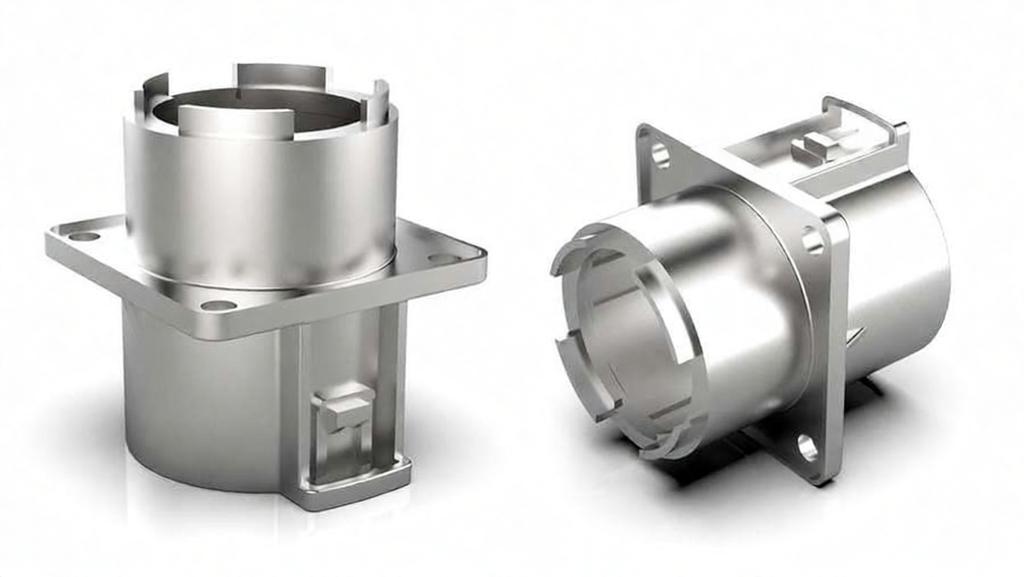
3. Performance & Capability: Side-by-Side Comparison
Once material compatibility is confirmed, you can compare the two processes across key performance and capability dimensions. Each process has clear strengths and tradeoffs.
| Comparison Metric | Metal Injection Molding (MIM) | High-Pressure Die Casting |
|---|---|---|
| Typical part weight | Several grams up to ~100g, focused on micro precision parts | 50g up to several kilograms, covers small to large parts |
| Geometric complexity | Very high; internal threads, cross holes, fine teeth possible | Moderate; strong for external features, internal features often require side actions |
| Minimum wall thickness | 0.3mm, excellent thin-wall forming capability | ~0.8mm; very thin walls risk cold shuts and incomplete fill |
| As-finished surface quality | High sintered surface finish, suitable for many end uses as-is | Wider range; as-cast surface is usually rougher |
| Mechanical properties | Near wrought properties; can be strengthened by heat treatment | Limited by gas porosity; welding and full solution heat treatment are not recommended |
| Production ramp-up time | Longer, requires sintering process development | Faster, fewer process steps to tune after mold completion |
Overall, MIM delivers the most value for small, complex, high-precision metal parts. Die casting delivers the best efficiency for medium to large non-ferrous structural parts produced at high volume.
4. Design Rules: Avoid Common Pitfalls for Each Process
Both processes have well-documented design constraints. Ignoring them at the drawing stage will lead to high defect rates, dimensional drift, or costly mold rework later in production. Early DFM review can eliminate most of these risks.
4.1 Key Design Rules for MIM
- Account for sintering shrinkage: MIM green parts shrink significantly during debinding and sintering. Shrinkage is predictable for uniform sections but becomes nonlinear at thick-to-thin transitions, which can cause warpage.
- Respect maximum wall thickness: overly thick sections prevent complete binder removal during debinding. Trapped carbon residue can embrittle stainless steel parts, even if they look visually correct.
- Support long overhangs: at sintering temperatures, the material softens and unsupported overhangs can sag. Ceramic supports can solve this but add tooling cost.
4.2 Key Design Rules for Die Casting
- Manage gas porosity: high-speed injection traps air inside the cavity. Porosity limits downstream operations like welding and solution heat treatment, and can cause surface blistering.
- Avoid cold shuts: when molten metal fronts cool before meeting, they form a visible line and a structural weak point. Gate location and runner design determine whether this occurs.
- Round internal corners: sharp inside corners create stress concentrations during solidification and are a common cause of hot tearing in service.
Both processes benefit greatly from early manufacturability review. PartsMastery provides free DFM analysis at the quotation stage to identify design risks before mold cutting begins.
5. Cost Structure: Where Your Money Goes
MIM and die casting have very different cost breakdowns. The most economical choice depends heavily on production volume, part complexity, and material cost.
| Cost Element | Metal Injection Molding (MIM) | High-Pressure Die Casting |
|---|---|---|
| Mold / tooling investment | Lower; injection happens at low pressure and temperature | Higher; molds must withstand molten metal and thermal cycling |
| Raw material cost | High; specialized metal powder feedstock is expensive | Low; standard ingot prices for aluminum and zinc |
| Material waste | Very low; nearly all feedstock becomes usable part | Higher; runners and gates generate recyclable scrap |
| Secondary machining cost | Low; most features form directly in the mold | Moderate; precision holes and threads usually require post-machining |
From a volume perspective, neither process amortizes its mold cost well at very low annual volumes. For quantities below a few thousand pieces per year, CNC machining is often the more economical choice.
At medium volumes, MIM becomes highly competitive for complex ferrous parts that would otherwise require many machining operations. At very high volumes, die casting wins decisively for non-ferrous parts thanks to its extremely short cycle times and low raw material cost.
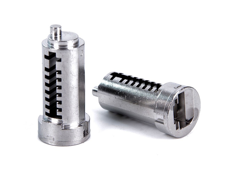
6. Selection Framework: Four Steps to the Right Process
You can quickly narrow down the best manufacturing process for your part by working through four sequential decision steps.
Step 1: Match your material first. If your part requires stainless steel, titanium, tool steel, or a high-temperature alloy, MIM will almost always be the better choice. If you are working with aluminum, zinc, or magnesium, die casting is usually the default solution.
Step 2: Check part size and weight. If your part weighs under 100g and fits within a 100mm envelope, MIM is well within its economic sweet spot. For larger and heavier parts, die casting will almost always be more cost-effective.
Step 3: Evaluate complexity and performance needs. If your design includes lots of internal features, fine geometries, or requires high mechanical strength, MIM will deliver more value per part. If your part is dominated by external features and you prioritize high output speed, die casting is the stronger option.
Step 4: Calculate total cost at target volume. Multiply per-piece cost by annual volume and add tooling and development cost. For small complex parts, MIM often comes out ahead at medium volumes. For large simple parts, die casting scales better at high volume.
7. Frequently Asked Questions
Can you die cast stainless steel?
No, stainless steel is not suitable for conventional die casting. Its very high melting point causes extreme thermal erosion and drastically shortens die life. For small stainless steel parts produced in volume, metal injection molding is the standard and most cost-effective solution.
What is the practical size limit for MIM parts?
Most production MIM parts weigh under 100 grams and measure less than 100mm in any direction. Above this range, uniform debinding and controlled shrinkage become much harder to achieve. Larger ferrous parts are usually better produced by investment casting or CNC machining.
Why are MIM molds made larger than the final part?
MIM parts shrink substantially during debinding and sintering as the binder is removed and metal particles densify. Mold cavities are scaled up by a precise shrinkage factor so that the final sintered part falls within the target dimensional tolerances.
What is the best way to prototype before committing to production tooling?
Neither MIM nor die casting tooling is fast or cheap for one-off parts. CNC machined prototypes are the industry standard for design validation before you invest in production tooling. PartsMastery can supply CNC prototypes in production-equivalent materials to test fit, form, and function.
Summary
MIM and die casting rarely compete head-to-head for the same part. In most cases, material selection alone will point clearly to one process or the other. When both are technically feasible, part size, complexity, and production volume become the deciding factors.
The most reliable manufacturing plans are designed for their process from the very beginning, not adapted as an afterthought. Early DFM review, realistic tolerance targets, and alignment between part geometry and process capability will give you the lowest risk and best overall value.