






When you pull a 3D printed part straight off the build plate, it almost never meets final end-use requirements right away. Layer lines, support marks, surface porosity, and internal residual stress can all compromise dimensional accuracy, functional reliability, and service life. Choosing the right post-processing method is critical to fixing these built-in printing limitations and bringing parts up to their designed performance targets.
This guide breaks down the as-built surface characteristics of major 3D printing technologies, explains how each mainstream post-processing method works, and outlines clear rules for matching processes to your needs. By the end, you will be able to plan optimal finishing strategies at the design stage, rather than treating them as an afterthought.
1. How Printing Technology Shapes Your Post-Processing Options
Each 3D printing process creates its own unique initial surface quality. This starting point directly dictates which post-processing methods will work well, and which will not deliver useful results. We can break down the most common technologies one by one.
1.1 FDM (Fused Deposition Modeling)
FDM builds parts layer by layer with extruded thermoplastic filament. Once you remove the support structures, you will usually see visible step-like layer lines and faint support scars on the surface. For this reason, the main post-processing goal for FDM parts is to smooth out these lines and create a more uniform, finished surface.
1.2 SLA / DLP (Resin Printing)
SLA and DLP parts come off the printer with a naturally smoother base surface than FDM parts, but they still carry uncured resin residue that you must wash away first. After washing, you need a UV post-cure step to bring the material to its full mechanical strength. For clear resin parts, you will also need extra polishing work to achieve true optical transparency.
1.3 SLS / MJF (Powder Bed Fusion)
SLS and MJF parts have a matte, slightly grainy texture straight out of the printer, with semi-fused powder particles stuck to the surface. Narrow channels and internal cavities often trap loose powder that you must remove before further finishing. Common next steps include bead blasting for uniform texture, dyeing for color, or chemical smoothing for a sealed, glossy finish.
1.4 Metal SLM (Selective Laser Melting)
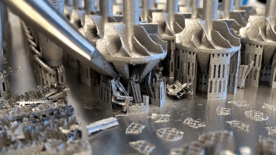
Metal 3D printed parts carry high internal residual stress and have a much rougher surface than machined components. Support removal also leaves visible witness marks that require secondary work. Unlike polymer parts, metal parts almost always need post-processing — you cannot skip stress relief and expect consistent, reliable performance.
| Printing Technology | As-Printed Surface | Core Post-Processing Goals |
|---|---|---|
| FDM | Visible layer lines, support scars, Ra 8–15 µm | Remove supports, smooth layer lines, improve surface uniformity |
| SLA / DLP | Smooth base surface with uncured resin residue | Wash and cure resin, reduce layer lines, add polish for clear parts |
| SLS / MJF | Matte, grainy surface with residual powder | Remove powder, bead blast, add dye or chemical smoothing |
| Metal SLM | Rough surface, high residual stress | Relieve stress, remove supports, finish critical faces with CNC machining |
2. Aesthetic Post-Processing: Improve Surface Look and Feel
All the processes in this category focus on visual and tactile improvements. They work only on the outer layer of the part, so they do not alter its core mechanical or material properties. We cover the three most widely used options below.
2.1 Manual Sanding and Polishing
First among aesthetic methods is manual sanding, which works with almost any material. You start with coarse grit paper to remove heavy layer lines, then step through progressively finer grits to smooth out scratches. For a near-mirror finish, you can continue all the way up to 2000+ grit and add a final polish.
For low-heat materials like PLA and PETG, wet sanding works best because it reduces friction heat that would melt or deform the surface. The main downside of manual sanding is its limitations with complex geometry. It cannot reach deep grooves, narrow holes, or intricate internal features, and labor costs rise quickly for high-precision work.
2.2 Chemical Smoothing
Next, chemical smoothing uses controlled solvent vapor to lightly melt the outer layer of a part. As the surface material reflows, layer lines disappear and you get a uniform, injection-molding-like finish. The process also seals surface porosity, which improves airtightness and water resistance.
Note that chemical smoothing only works with specific materials. It delivers excellent results on ABS, ASA, and nylon materials like PA12 and PA11, but it does not work at all on PLA or PETG. It also causes very slight dimensional changes, so you should account for this in your design.
2.3 Tumbling and Vibratory Finishing
For batch processing of many small parts at once, tumbling and vibratory finishing offer the best efficiency. You load parts into a tub or barrel along with abrasive media, and constant friction wears away sharp edges and rough surfaces. Different media types produce different results — ceramic cuts fast for heavy deburring, while walnut shell delivers a soft, polished luster.
On the downside, these processes cannot reach internal channels or deep cavities. They also tend to round off sharp edges and fine details, so you should review part geometry before choosing this method.
| Finishing Process | Compatible Materials | Roughness Improvement | Key Limitation |
|---|---|---|---|
| Manual sanding | Most plastics and some metals | From Ra 8–15 µm down to 1–3 µm | Cannot reach deep features; high labor cost |
| Chemical smoothing | ABS, ASA, PA12, PA11 | From Ra 8–15 µm down to 0.8–2 µm | Narrow material compatibility; slight size change |
| Tumbling / vibratory finishing | Metals, durable polymers | From Ra 10–15 µm down to 3–6 µm | Cannot reach internal channels; rounds fine edges |
3. Functional Post-Processing: Boost Mechanical and Chemical Performance
Beyond surface appearance, many functional parts require post-processing that improves their mechanical, chemical, or electrical properties. These processes go deeper than cosmetic fixes — they alter the material itself to meet stricter end-use demands.
3.1 Annealing and Stress Relief
First and most widely used is annealing, often called stress relief for metal parts. It uses a carefully controlled heating-holding-cooling cycle to release internal stress that builds up during printing. For metal parts, this step is almost mandatory because it prevents deformation or cracking during later machining or real-world use.
For polymer parts, the benefits vary by material. Annealing can raise the heat deflection temperature of PLA significantly. For high-performance materials like PEEK and ULTEM, it improves crystallinity and boosts overall mechanical performance. Keep in mind that annealing always causes some material shrinkage, so you should build this into your design tolerances.
3.2 Epoxy Coating and Vacuum Impregnation
If you need a sealed, chemically resistant surface, epoxy coating or vacuum impregnation will deliver the best results. Hand brushing works well for small batches and visible outer surfaces. For deeper, more uniform sealing of porous parts, vacuum impregnation pulls resin into the surface pores for a full seal.
Both methods add a small amount of thickness to the part surface. For parts with tight mating features, you should plan for this extra thickness ahead of time.
3.3 Bulk Dyeing
For SLS and MJF nylon parts, bulk dyeing is the standard way to add consistent, long-lasting color. You submerge parts in a heated dye bath, and the color penetrates about 0.5 mm into the material surface.
Unlike paint, dyeing adds no extra coating thickness, and it will not chip, peel, or wear off with normal handling. Darker colors generally deliver the most consistent and colorfast results.
3.4 Electroplating
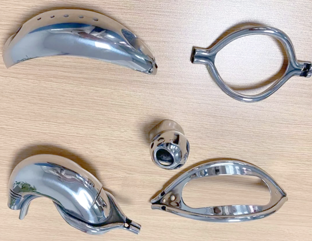
Finally, electroplating deposits a real metal layer onto the surface of a polymer part. You can choose copper for electromagnetic shielding, nickel for corrosion resistance and surface hardness, or chrome for a mirror-like decorative finish.
You can only plate materials that accept a conductive base layer; ABS and photopolymer resins work best. Masking adds extra labor cost if you need to keep threads or mating faces free of plating.
4. Precision Mechanical Post-Processing for Tighter Tolerances
Sometimes 3D printing alone cannot deliver the dimensional accuracy you need for assembly-critical features. In these cases, secondary mechanical post-processing provides a reliable path to machined-grade precision without remaking the entire part.
4.1 Secondary CNC Machining
The core idea here is simple: print to get the overall shape, then machine to get functional precision. 3D printing forms the full part structure, then CNC milling finishes critical features like datum surfaces, sealing faces, mounting holes, and threads to meet strict tolerance standards.
PartsMastery offers both printing and CNC machining in-house, so you do not need to coordinate multiple suppliers. This closed-loop workflow reduces lead time, cuts alignment errors between processes, and keeps full quality accountability in one place.
4.2 Heat-Set Threaded Inserts
Printed plastic threads wear out quickly with repeated assembly and disassembly. Heat-set threaded inserts solve this problem completely. You press a knurled metal insert into a pre-drilled hole with heat, and as the plastic cools it shrinks tightly around the insert for a permanent, strong connection.
Installed inserts deliver far higher pull-out and torque resistance than printed threads. Standard sizes from M2 to M8 work for most enclosure, jig, and functional component applications.
5. How to Select the Right Post-Processing Workflow
Post-processing is not a one-size-fits-all add-on. You should match your process choice to the specific needs of each part. You can narrow down your options systematically by answering four core questions.
- What will the part be used for? Visual prototypes prioritize surface appearance, functional test parts prioritize dimensional accuracy, and end-use production parts balance performance and cost.
- What material is the part made of? Material compatibility is a hard filter — some processes only work with specific plastics or metals.
- How tight are the tolerance requirements? Any process that removes or adds material will change part dimensions. Plan accordingly for features with tight fit requirements.
- How many parts do you need? Manual methods work well for low volumes, while batch processes deliver much better cost efficiency for larger quantities.
| Application Scenario | Top Priority | Recommended Process Path |
|---|---|---|
| Visual prototypes / display models | Surface appearance and finish quality | Sanding + primer and top coat, or chemical smoothing |
| Functional test parts / jigs | Dimensional accuracy and durability | Support removal + light sanding, plus threaded inserts if needed |
| End-use polymer parts | Balanced surface, performance, and cost | Bead blasting or tumble finishing + dyeing or chemical smoothing |
| End-use metal parts | Structural integrity and precision | Stress relief + CNC machining at critical interfaces |
| Consumer-facing enclosures | Premium appearance and wear resistance | Chemical smoothing + epoxy and paint, or electroplating |
6. Frequently Asked Questions
Can I skip post-processing for simple functional prototypes?
For basic internal brackets and jigs where surface finish does not matter, you can often use parts as-printed. But if you need to verify assembly fit, sealing performance, or tight clearances, skipping post-processing can hide true dimensional gaps and give you misleading test results. When in doubt, plan at least minimal finishing for fit-critical features.
What is the fastest post-processing method for FDM parts?
For ABS and ASA parts, vapor smoothing is by far the fastest option. It can finish an entire batch in just a few minutes and delivers much more uniform results than hand sanding. For PLA materials, there is no equivalent fast chemical method, so sanding or coating remains the standard approach.
When should I choose CNC machining instead of manual finishing?
Choose CNC machining whenever you need guaranteed dimensional accuracy, consistent tolerances, or repeatable results across a batch. Manual finishing can make a surface look smooth, but it cannot correct geometric errors or hold tight position tolerances. Datum faces, sealing surfaces, and threaded holes almost always perform better with CNC finishing.
Does heat treatment change the size of metal 3D printed parts?
Yes, heat treatment causes minor but predictable dimensional changes and slight distortion as internal stress releases. With proper process planning, you can compensate for these changes in the print model and hit your target final dimensions. Always factor heat treatment into your tolerance plan for critical metal parts.
Summary
The most reliable post-processing strategy is the one you plan before you start printing. Start with your printing technology and base material, then match processes to your actual functional and aesthetic requirements, and design with finishing tolerances in mind from the beginning.
PartsMastery provides a full range of 3D printing and supporting post-processing services, covering everything from early prototype validation to low-volume production. You can upload your CAD files at any time to receive a free DFM manufacturability review, including tailored post-processing recommendations and a full quotation.