


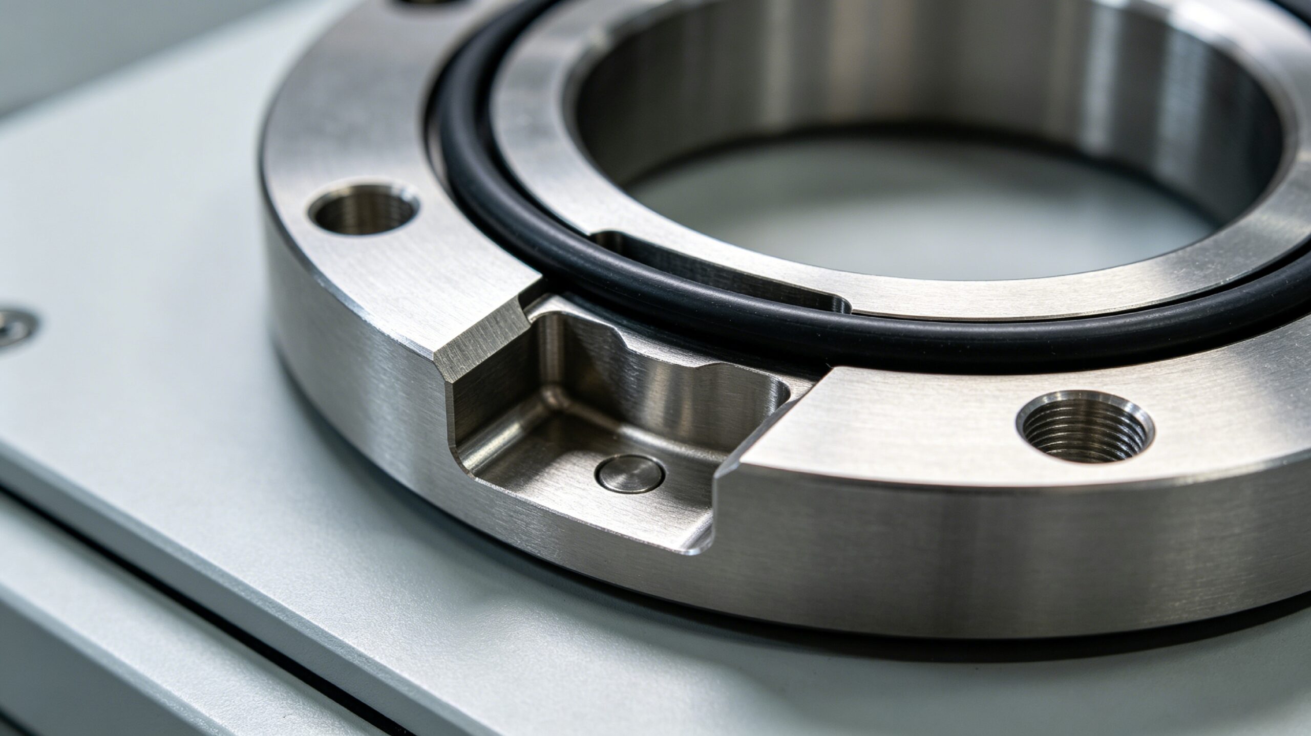
In static seal engineering design, engineers must properly position O-rings to improve assembly efficiency and seal reliability. The dovetail groove is a necked special-shaped seal groove. It uses a mechanical locking structure to hold O-rings in place and prevent them from falling out. This design solves a common problem: ordinary straight grooves often allow seals to shift or drop during vertical installation and repeated disassembly.
Unlike rectangular straight grooves, which rely on compression force to hold seals in place, dovetail grooves use inclined side walls to create an inner-narrow, outer-wide clamping structure. This design restrains the O-ring inside the groove even when no compression is applied. It greatly improves stability during assembly and maintenance. However, this complex shape also demands higher design accuracy and more precise machining.
This article breaks down the entire engineering design and manufacturing process of dovetail grooves. It covers structural principles, dimension specifications, processing techniques, design key points, material selection, and application scenarios. It provides a complete technical reference for seal design and precision machining practitioners.
1. Structural Definition and Locking Principle of Dovetail Grooves
1.1 Basic Definition and Geometric Characteristics
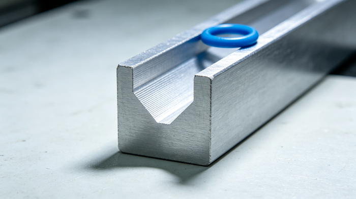
A dovetail groove is a special-shaped groove with a “necked trapezoidal” cross-section. Its notch width is smaller than its groove bottom width, and its two side walls incline outward along the depth direction. This shape forms a built-in clamping structure.
In sealing systems, this structure mechanically restrains the O-ring inside the groove cavity. It achieves axial positioning of the seal without relying on compressive force.
1.2 How the Anti-Detachment Locking Works
In ordinary rectangular straight grooves, the O-ring only stays fixed after assembly. At that point, the upper and lower end faces squeeze the O-ring and create friction. In an unassembled or open state, gravity and vibration can easily cause the seal to shift or fall out.
The dovetail groove solves this problem with an inclined side wall that acts like a “barb.” It creates radial constraint on the O-ring cross-section. When the O-ring tries to leave the groove under external force, the inclined wall pushes back and clamps the seal. This prevents the O-ring from pulling out of the narrow notch, so the seal stays in place even when uncompressed.
1.3 Core Structural Components
A complete dovetail groove structure includes four key geometric features. Together, they determine both the limiting effect and sealing performance:
- Notch width: It controls installation difficulty and anti-detachment strength. A narrower notch improves retention but increases installation resistance.
- Groove depth: It controls the O-ring compression ratio and directly affects sealing specific pressure.
- Sidewall inclination angle: It determines locking force. Industry commonly uses 55° to 70°, balancing anti-detachment effect and processing feasibility.
- Bottom corner radius: It is the transition fillet between the groove bottom and side wall. It directly affects O-ring installation safety.
2. Application Value and Scenario Boundaries of Dovetail Grooves
2.1 Core Performance Advantages
- Prevents seal detachment in an uncompressed state
This is the most important value of a dovetail groove. In vertically installed flanges, vertically arranged cover plates, and cavities that require frequent opening, straight-groove O-rings often fall out due to gravity and vibration. The mechanical clamping of dovetail grooves holds the seal firmly in place. It greatly reduces the risk of seal misalignment and falling during assembly and maintenance.
- Improves sealing stability during assembly
During assembly, especially with flanges that use bolt step-by-step locking, thrust can easily shift the seal. This shift may cause insufficient local compression and lead to leakage. The dovetail groove restricts the O-ring to the designed position. It reduces displacement deviation during assembly and improves the sealing qualification rate.
- Improves reusability of maintainable components
Equipment that requires regular disassembly and maintenance often suffers from seal displacement and distortion after repeated handling. This increases the probability of seal failure. The dovetail groove ensures the seal remains in its initial position after each opening. It simplifies maintenance and reduces seal loss.
2.2 Applicable Scenario Boundaries
Dovetail grooves work best in static sealing conditions. Engineers should not use them for dynamic sealing scenarios.
In dynamic sealing, the O-ring moves back and forth or rotates with moving parts. The necked structure of a dovetail groove increases edge wear on the seal. At the same time, the inclined side wall can cause the seal to extrude and fail under pressure. This shortens seal life significantly. Therefore, dovetail grooves are primarily an optimization scheme for static face seals.
3. Dimensional Design Specifications and Parameter System
3.1 Two Major Dimensional Standard Systems
Global dovetail groove size design follows two main systems: imperial and metric. Each system corresponds to different O-ring standards:
- Imperial system: It is based on AS568 standard O-ring sizes. It is widely used in industrial equipment and aerospace in the North American market. Sizes are based on inches and correspond to a complete series of groove parameters.
- Metric system: It corresponds to ISO standard metric O-rings. It is widely used in Europe and China. Engineers usually recommend dovetail groove structures for O-rings with a cross-sectional diameter of 3.53 mm or larger. This ensures sufficient structural strength and limiting effect.
3.2 Standard Groove Types vs. Customized Design
- Standard size groove types: They work well when O-ring selection and assembly structure follow general specifications. Designers can select them directly from industry standard manuals. They lower design cost and use mature processing technology.
- Customized groove types: They are needed when equipment has space constraints, non-standard sealing surface layouts, or special working conditions. Engineers must adjust groove width, depth, and angle according to actual conditions. Custom design requires verification of both seal compression ratio and anti-detachment locking force to ensure performance.
3.3 Design Logic of Core Dimensional Parameters
Each dimensional parameter serves a clear performance goal. Designers must balance sealing performance and processing feasibility:
- Groove width: It determines the lateral clearance of the O-ring inside the groove. It must support both easy installation and proper compression filling rate. Dovetail groove width includes notch width and groove bottom width, both determined by the sidewall inclination angle.
- Groove depth: It directly controls O-ring compression ratio and is the most sensitive parameter for sealing performance. Static seal compression ratio usually ranges from 15% to 30%. Too much deviation in groove depth may cause insufficient compression leakage or over-compression damage to the seal.
- Sidewall inclination angle: It determines locking force. A smaller angle creates a more obvious necking and stronger anti-detachment force, but it also increases processing difficulty and raises the risk of seal damage during installation. The industry typically uses 60° to 66°, balancing performance and manufacturability.
- Bottom corner radius: The groove bottom fillet avoids stress concentration and protects the O-ring from sharp edges during installation. Too small a fillet radius may cut the seal. Too large a fillet occupies sealing space and increases extrusion risk. Designers must match it to the O-ring cross-section size.
- Surface roughness: Groove wall and groove bottom surface quality directly affect sealing effect. For gas sealing conditions, the recommended surface roughness is ≤Ra1.6. For liquid sealing conditions, it can be relaxed to Ra3.2. Excessively high roughness creates leakage channels, while too low roughness increases processing cost.
| AS568 Series Number | O-ring Cross-section Diameter (inch) | Nominal Groove Bottom Width (inch) | Nominal Groove Depth (inch) | Bottom Fillet Radius (inch) |
|---|---|---|---|---|
| -000 Series | 0.070 | 0.070 | 0.064 | 0.015 |
| -100 Series | 0.103 | 0.103 | 0.088 | 0.015 |
| -200 Series | 0.139 | 0.139 | 0.120 | 0.031 |
| -300 Series | 0.210 | 0.210 | 0.176 | 0.031 |
Note: The table shows basic reference values for imperial standard dovetail grooves. Actual design requires adjusted tolerances and margins based on specific working conditions and material characteristics.
4. Mainstream Processing Technologies and Selection Comparison
Dovetail grooves have a special-shaped structure that cannot be formed in a single process. Manufacturers must select the appropriate processing technology based on workpiece size, material, and accuracy requirements. The industry currently uses four main technologies: CNC milling, planing, wire EDM, and grinding.
4.1 CNC Milling
CNC milling is currently the most widely used dovetail groove processing technology. It works well for small and medium-sized parts and mass production scenarios.
- Processing flow: It usually includes two steps. First, an end mill rough machines a rectangular straight groove and removes most of the allowance. Then, a special dovetail forming milling cutter machines the two inclined planes and forms the complete groove shape. Some small groove types can also be processed in one step with an integrated forming cutter.
- Process advantages: It provides high dimensional accuracy, good batch consistency, and high processing efficiency. It works with most materials, including aluminum alloy, stainless steel, and plastic.
- Applicable scenarios: It suits dovetail groove processing for industrial equipment covers, flanges, and hydraulic valve bodies. It is the preferred process for small and medium batch production.
4.2 Planing and Slotting Processing
Planing and slotting are traditional cutting processes. They still play an irreplaceable role in dovetail groove processing for large and heavy workpieces.
- Process characteristics: They use a single-point tool to remove material in a reciprocating linear motion. They can machine internal dovetail grooves and deep groove structures on large workpieces. The equipment cost is low, but processing efficiency and automation level are not high.
- Applicable scenarios: They suit dovetail groove processing for large machine tool guide rails, heavy equipment bases, and large-size internal groove structures. They are mostly used for single-piece and small-batch heavy equipment production.
4.3 Low-Speed Wire EDM Processing
Wire electrical discharge machining is a non-contact processing method. It relies on spark discharge to erode materials without cutting force. It suits high-precision, high-hardness material narrow groove processing.
- Process advantages: It can machine extremely hard materials such as tool steel and cemented carbide. It achieves groove profile accuracy of ±0.005 mm, good surface quality, and no burrs. It also requires no special forming tool and can flexibly machine special-shaped groove types with any angle.
- Limitations: It has low processing efficiency and high cost. It can only process through groove bodies, not blind grooves.
- Applicable scenarios: It suits high-precision through dovetail groove processing for precision molds, tooling fixtures, and cemented carbide parts.
4.4 Grinding Finishing
Grinding is a finishing process. It improves groove accuracy and surface quality after rough machining.
- Process characteristics: It uses a forming grinding wheel to grind the groove wall and groove bottom. It achieves extremely high geometric accuracy and extremely low surface roughness. It can also correct deformation after heat treatment.
- Applicable scenarios: It suits scenarios with extremely high requirements for surface quality and straightness, such as machine tool sliding guide rails, high-precision sealing reference surfaces, and high-demand vacuum sealing grooves.
| Processing Technology | Core Applicable Scenarios | Dimensional Accuracy Grade | Production Efficiency | Compatible Materials |
|---|---|---|---|---|
| 数控铣床 | Small and medium parts, mass production, blind grooves/through grooves | IT7~IT8 | 高 | Most metals and engineering plastics |
| Planing/Slotting | Large heavy workpieces, internal dovetail grooves, single-piece small batch | IT8~IT9 | 低 | Mainly metal materials |
| Low-Speed Wire EDM | High-precision hard materials, through grooves, special-shaped angles | IT5~IT6 | 低 | Conductive metal materials, especially suitable for high-hardness alloys |
| Grinding Processing | High-precision guide rails, high surface quality sealing surfaces, finishing after heat treatment | IT4~IT5 | 中低 | Metal materials, especially hardened steel |
5. Technical Difficulties and Quality Control
Dovetail grooves have an undercut structure that increases processing difficulty. Quality control focuses on four main dimensions.
5.1 Tool Path Planning for Special-Shaped Grooves
Dovetail grooves have a laterally concave undercut structure. Manufacturers cannot form them in one simple layered milling pass like straight grooves. In CNC machining, programmers must plan roughing and finishing tool paths carefully. This ensures accurate sidewall angles and avoids interference between the tool and the groove sidewall. For small-size dovetail grooves, the cutting edge accuracy of the forming tool directly determines groove quality. Operators must check tool wear regularly.
5.2 Geometric Accuracy Control of Internal Corners and Side Walls
Groove wall angle deviation and straightness error directly affect locking effect and sealing performance. This is especially true at the bottom corner position. Limited by tool fillet, overcut or residual allowance often occurs. This may cause the fillet radius to fall outside design requirements and increase the risk of seal scratching. During processing, operators must control key dimensions such as angle, fillet, and side wall straightness. They can use coordinate measuring machines (CMM) and profilometers for inspection.
5.3 Edge Deburring and Surface Quality Control
Dovetail grooves easily develop cutting burrs at the notch edge and side wall junction. Dovetail grooves for sealing have zero tolerance for burrs. Even tiny burrs may scratch the O-ring during assembly or use and cause seal failure. Therefore, after processing, operators must treat all sharp edges with manual deburring, abrasive flow polishing, or similar processes. This ensures edges are blunted and smooth. It also helps control internal surface roughness to meet design requirements.
5.4 Dimensional Stability in Batch Production
In batch processing, tool wear, material hardness fluctuation, and clamping deformation may cause groove size deviation. This is especially true for depth and angle. Small cumulative errors may lead to excessive compression ratio or insufficient anti-detachment force. Therefore, manufacturers must set up first article inspection and in-process sampling inspection mechanisms. They should also apply SPC statistical process control for key dimensions to ensure batch consistency.
6. Material Selection Guide for Dovetail Groove Processing
Material mechanical properties and cutting characteristics directly determine processing feasibility and final performance. Engineers must select materials based on working condition requirements.
6.1 Metal Material Selection
Metal materials are the most widely used matrix materials for dovetail grooves. Different alloys show significant differences in performance and processing characteristics:
- Aluminum alloy (6061/7075/5052): It offers excellent cutting performance, high processing efficiency, light weight, and good corrosion resistance. It is the preferred material for sealing grooves in civil industrial equipment and electronic equipment. It suits mass CNC processing.
- Stainless steel (304/316L): It provides strong corrosion resistance and works well in harsh chemical, medical, and food conditions. It also has high strength. However, it has poor machinability and large cutting load. During processing, operators must control tool wear and thermal deformation. It is mostly used for sealing structures in fluid equipment and medical equipment.
- 黄铜: It offers excellent cutting performance, stable size, and good electrical and thermal conductivity. It suits small dovetail groove processing for precision instruments and pneumatic components. However, it has limited strength and does not work well in high-pressure heavy-load conditions.
- 碳钢: It has high strength and low cost. It suits heavy-load structural dovetail grooves for general machinery. However, it easily corrodes and requires surface plating or coating treatment. It is mostly used for internal structural parts.
- Tool steel: It has high hardness and good wear resistance. It can achieve extremely high surface strength after heat treatment. It is mostly used for dovetail groove structures in molds, fixtures, and machine tool guide rails. However, it has high processing difficulty and usually requires wire EDM or grinding.
6.2 Engineering Plastic Selection
Engineering plastic dovetail grooves are mostly used in scenarios that require lightweight, corrosion resistance, and insulation. Engineers must select materials with stable size and easy processing:
- POM(聚氧甲烯): It offers excellent dimensional stability, good cutting performance, and high strength. It is the preferred material for dovetail grooves in precision plastic parts. It is widely used in pneumatic components and small equipment structures.
- 尼龙: It has good toughness, excellent wear resistance, and self-lubricating properties. It suits sliding fit dovetail groove structures. However, it has strong hygroscopicity, and environmental humidity easily affects its dimensional accuracy. For high-precision scenarios, manufacturers must perform moisture absorption treatment.
- PTFE (Polytetrafluoroethylene): It has extremely strong corrosion resistance and extremely low friction coefficient. It suits sealing grooves in strong corrosion conditions. However, the material is soft and easily produces deformation and burrs during processing. It requires a low-speed fine cutting process.
- PEEK (Polyetheretherketone): It has high strength, high temperature resistance, and chemical corrosion resistance. It offers excellent overall performance and works well in high-end conditions such as medical and aerospace. However, it has high material cost and high processing difficulty.
- UHMW-PE (Ultra High Molecular Weight Polyethylene): It has strong impact resistance and low friction coefficient. It suits dovetail groove structures for large light industrial equipment. However, it has low stiffness and poor applicability in high-precision scenarios.
6.3 How Material Properties Affect Processing Technology
Material hardness and toughness are the core factors that affect processing schemes:
- High hardness materials such as hardened tool steel: Manufacturers should prioritize wire EDM and grinding processes to avoid excessive milling tool wear.
- Soft plastic materials such as aluminum alloy and PTFE: Manufacturers must focus on burr and edge deformation control. They should use sharp tools, high-speed cutting, and deburring processes.
- Brittle materials: Manufacturers must control cutting feed rate to avoid chipping at the notch edge, which would affect sealing performance.
7. Application Scenarios and Covered Industries
Dovetail grooves are an optimized groove type for static seals. They are widely used in industrial scenarios that require assembly stability and maintainability.
7.1 Core Application Scenarios
- Bolted flange seals: Especially for vertically installed flanges, dovetail grooves prevent O-rings from falling off due to gravity during assembly. They improve assembly efficiency and sealing reliability.
- Detachable equipment covers: For cavities and cabinets that require regular opening for maintenance, the seal remains in place during repeated disassembly and assembly. This greatly simplifies the maintenance process.
- Vacuum equipment chambers: Vacuum sealing has high requirements for seal position accuracy. The limiting effect of dovetail grooves prevents vacuum leakage caused by seal misalignment.
- Hydraulic and pneumatic valve covers: These are end face seals for valve bodies and cylinder heads. They ensure that seals do not fall off during equipment maintenance and repair, and reduce maintenance difficulty.
7.2 Covered Industry Fields
- Industrial equipment manufacturing: It uses dovetail grooves for box and cover seals in general machine tools, automation equipment, and packaging machinery. This is the largest application field for dovetail grooves.
- Hydraulic and pneumatic industry: It uses dovetail grooves for end cover seals in valve bodies, oil cylinders, and air cylinders. These meet static sealing requirements under high-pressure conditions.
- Fluid and vacuum equipment: It uses dovetail grooves for sealing structures in pump bodies, valves, vacuum chambers, and semiconductor manufacturing equipment. These applications demand extremely high sealing stability.
- Aerospace and precision manufacturing: It uses dovetail grooves for sealing structures in airborne equipment, precision instruments, and medical equipment. These applications have strict requirements for dimensional accuracy and reliability.
- Customized sealing engineering: It uses custom sealing structures for non-standard equipment and special tooling. Engineers design customized dovetail grooves according to actual needs.
8. FAQ on Common Engineering Problems
Q1: What is the standard processing flow of dovetail grooves on steel?
A: Steel dovetail groove processing usually follows this flow: rough machining → finish machining → deburring → inspection. First, an end mill mills a rectangular straight groove and leaves a finishing allowance of 0.2 to 0.5 mm. Then, a special dovetail forming milling cutter machines the two inclined planes at a lower cutting speed. This ensures angle and dimensional accuracy. After processing, operators perform deburring and blunting on the notch and groove bottom edges. Finally, they inspect key dimensions and surface quality with a CMM and roughness tester. For high-hardness steel, manufacturers can perform rough machining first and then use grinding after heat treatment to ensure accuracy.
Q2: What is the core difference between dovetail grooves and ordinary straight grooves in sealing performance?
A: The core difference is not sealing capacity itself. It lies in seal retention and assembly stability.
With correct assembly and no seal displacement, both well-designed straight grooves and dovetail grooves can achieve the same static sealing effect. However, in unassembled, maintenance, and vertical installation scenarios, the mechanical locking structure of the dovetail groove ensures that the O-ring does not shift or fall out. This greatly reduces the risk of seal failure caused by assembly errors. Straight grooves have a simple structure and low processing cost. They suit horizontally arranged sealing scenarios with fixed installation and no frequent disassembly.
Q3: What is the difference in mechanical properties between dovetail tenon structures and ordinary tenon groove structures?
A: The core difference lies in tensile pull-out capacity. The inclined side wall of the dovetail tenon forms a mechanical locking structure. Its axial tensile pull-out force is much higher than that of ordinary straight tenon grooves. It can achieve fastener-free mechanical clamping connection. It is often used for sliding connections in furniture, wood structures, and machine tool guide rails.
Ordinary straight tenon grooves mainly perform positioning and fitting functions. They only rely on friction or fasteners to provide connection force. They have weak anti-separation ability, but they have a simple structure and low processing difficulty. They suit connection scenarios that require high positioning accuracy and do not bear strong pull-out force.
Q4: What is the core calculation logic of dovetail groove size design?
A: Dovetail groove design for sealing takes the O-ring cross-sectional size as the core reference. The calculation logic has three steps:
- Determine the compression ratio: Engineers determine the target compression ratio of the O-ring based on working conditions such as gas/liquid and pressure level. Then they reverse the required groove depth size.
- Match groove width and angle: Engineers select a standard side wall angle, usually 60° to 66°, based on O-ring cross-section diameter. Then they calculate the groove bottom width and notch width. This ensures the seal can install smoothly and has sufficient locking force.
- Check fillet and clearance: Engineers match the bottom corner radius and check the filling rate of the seal after compression. This avoids extrusion risk.
In actual design, engineers can directly refer to the corresponding standard size manual and then make fine adjustments based on actual working conditions.
结论
The dovetail groove is an optimized static seal design that balances reliability and practicality. It uses a simple mechanical clamping structure to solve the common problem of seals falling out during frequent disassembly and vertical installation. However, the special-shaped structure also raises requirements for design accuracy and processing technology. Engineers must match dimensional parameters reasonably, select appropriate processing technology, and strictly control key quality nodes to fully utilize the performance advantages of dovetail grooves.
In practical engineering applications, engineers must evaluate the performance benefits and processing costs of dovetail grooves based on specific working conditions and cost requirements. Then they can select the most suitable sealing groove scheme.