






Stainless steel is widely used across aerospace, medical equipment, food processing, and automotive industries for its excellent corrosion resistance and strong mechanical properties. However, its low thermal conductivity, high work hardening risk, and tough microstructure make stainless steel cutting one of the most challenging tasks in metal fabrication. When operators fail to control parameters properly, they often face rapid tool wear, heavy burrs, material deformation, and edge discoloration — all of which directly reduce production efficiency and compromise final part quality.
For this reason, this guide breaks down the full technical workflow of stainless steel cutting, covering process selection, standard operating steps, key parameter tuning, and fixes for common defects. In short, it provides machining professionals and shop floor teams with a practical, easy-to-follow reference for daily use.
1. Technical Fundamentals and Core Challenges of Stainless Steel Cutting
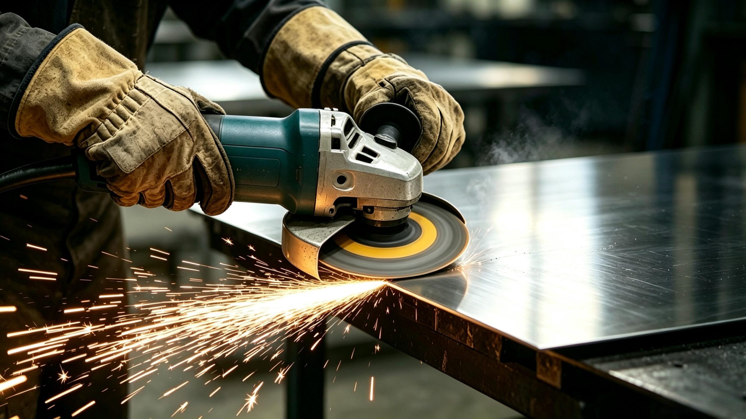
Simply put, stainless steel cutting separates material through mechanical shearing, high-energy beam melting, or abrasive erosion. It serves as a core step in sheet metal forming, rough machining, and blanking operations. In fact, the cutting method you choose and how you set your parameters directly determine edge quality, dimensional accuracy, and total processing cost.
Compared with ordinary mild steel, stainless steel poses noticeably higher cutting difficulty. This gap stems from three key material characteristics:
1.1 Strong Work Hardening Effect
First, common grades such as austenitic stainless steel undergo surface plastic deformation under cutting forces. This deformation quickly raises dislocation density and forms a work-hardened layer far harder than the base material. As a direct result, this hardened layer increases cutting resistance and speeds up wear on the tool cutting edge.
1.2 Low Thermal Conductivity
Furthermore, stainless steel conducts only about one-third as much heat as mild steel. For this reason, heat generated during cutting cannot spread quickly through the workpiece, and most of it concentrates at the cutting edge. This heat buildup easily leads to tool overheating and softening, significantly shortens tool life, and causes oxidative discoloration on the cut surface.
1.3 High Toughness and Ductility
Finally, stainless steel has high fracture toughness, so chips do not break cleanly on their own. This issue often leads to built-up edge formation and chip tearing during machining. Over time, these problems create more burrs on the cutting edge and degrade surface finish.
2. Standard Operating Procedure for Stainless Steel Cutting
A clear, repeatable workflow forms the foundation for consistent cut quality and longer tool life. Whether you use hand tools or CNC equipment, following these seven core steps will deliver reliable cutting results. For easier understanding, we divide them into three stages: pre-cut preparation, in-process control, and post-cut finishing.
Step 1: Precise Dimension Marking and Layout
Good dimensional accuracy starts before any cut begins, with careful marking and layout. For high-precision jobs, use a carbide scriber instead of an oil-based marker to draw thinner, sharper guide lines. You should also double-check critical dimensions with tools like vernier calipers and height gauges to avoid wasting material from marking errors. For mass production runs, meanwhile, custom positioning templates or fixtures work very well to remove cumulative errors from hand marking.
Step 2: Rigid Clamping and Workpiece Fixturing
Next, lock the workpiece firmly in place before you start cutting. Stainless steel is strong and tough, so loose clamping will quickly cause cutting vibration, chatter marks and even broken blades. Pick your clamping method to match the workpiece shape. Thin sheets need rigid backing plates to reduce bending during cutting. Round tubing requires perfect axis alignment with the cutting direction to avoid oval-shaped cuts. Irregular parts work best with custom tooling to keep clamping force even and prevent loose spots.
Step 3: Tool and Saw Blade Selection and Matching
Always choose tools and blades made specifically for stainless steel. Carbide-tipped or high-performance bimetal saw blades work best, as their heat and wear resistance fit the material’s unique properties. Specifically, match the tooth pitch (Teeth Per Inch, TPI) to your material thickness. Use 18–24 TPI fine-tooth blades for sheets 1.5mm or thinner for smooth cuts. Use 10–14 TPI coarse-tooth blades for materials thicker than 5mm for better chip removal and less heat buildup.
Step 4: Cutting Parameter Presetting and Calibration
After you pick your tool, set and test your cutting parameters carefully. As a general rule, stainless steel works best at 50%–70% of the cutting speed used for mild steel. For this reason, you should lower the equipment speed to match your material thickness and tool type. Before full production runs, do a test cut on scrap material to check spark patterns and cut quality, then tweak the settings to the best range. Set your feed rate ahead of time to avoid random speed changes in the middle of a cut.
Step 5: Thermal Management During Cutting
Controlling temperature in the cutting zone is the most important step for consistent results. For the best outcome, use spray cooling with emulsion or specialized cutting fluid, or blow chips away with compressed air to reduce heat. When cutting thick material, by contrast, use an intermittent feed strategy to let heat escape between cuts. Never hold the tool in one spot for too long, since localized overheating can change the material’s internal structure.
Step 6: Post-Cut Edge Finishing and Deburring
Once you finish the cut, move on to edge finishing and deburring. Burrs and sharp edges almost always show up after mechanical cutting, and they can cause assembly problems and safety risks if left alone. Use files, rotary deburring tools or grinding wheels to smooth edges and remove sharp corners. If you see thermal discoloration on the cut edge, apply pickling passivation or light polishing to restore the stainless steel’s protective film and keep its corrosion resistance strong.
Step 7: Finished Dimensional and Geometric Verification
Last but not least, check all finished parts before moving to assembly. Measure key dimensions including length, straightness, perpendicularity and cut flatness. For long, thin workpieces, pay extra attention to any warping or bending. Catching dimensional issues early prevents rework during later assembly and welding steps and keeps total production costs down.
3. Comparison and Selection Guide for Mainstream Cutting Processes
3.1 Classification of Common Cutting Methods
You can group stainless steel cutting processes into three main categories: CNC precision machining, industrial thermal cutting and general workshop tools. Each method differs a lot in accuracy, speed, cost and suitable thickness, so you should match your choice to your specific production needs. Generally speaking, CNC processes deliver the highest precision, thermal methods offer the fastest speed, and workshop tools provide the most flexibility for on-site jobs.
3.2 Performance Comparison Across Key Metrics
The table below compares eight mainstream processes across seven core performance metrics. This side-by-side view helps you quickly evaluate which method fits your project best.
| Cutting Process | Primary Applications | Thickness Range | Edge Quality | Processing Speed | Heat-Affected Zone | Overall Cost |
|---|---|---|---|---|---|---|
| CNC Milling | Complex cavities, precision feature machining | Solid stock / irregular structural parts | High precision, controllable surface finish | Moderate | Very low (controlled cutting) | Medium to high |
| CNC Turning | Shafts, sleeves and rotary parts | Cylindrical / bar workpieces | High precision, excellent concentricity | High | Very low (controlled cutting) | Medium to high |
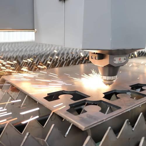
| Laser Cutting | Precision thin-sheet blanking, complex contours | Thin to medium plates (up to ~30mm) | Excellent, minimal burrs, no secondary finishing | High (CNC automated) | Small, slightly increased for thick plates | High |
| Plasma Cutting | Fast blanking of medium-thick plates | Medium-thick plates | Moderate, edges require subsequent cleaning | Very high | Significant, deep HAZ for thick materials | Medium |
| Waterjet Cutting | Thick plates, heat-sensitive materials | Full range from thin to ultra-thick plates | Excellent, clean edges with no thermal damage | Moderate | None (cold working process) | High |
| Circular Saw Cutting | Workshop straight-line sheet blanking | Thin to medium-thick sheets | Good, regular straight cuts | Moderate | Small | Low |
| Band Saw Cutting | Fixed-length blanking of tubes and bars | Tubes, bars, profiles | Good, minimal burrs | Moderate | Very low | Low to medium |
| Angle Grinder Cutting | On-site operations, small-batch trimming | Thin to medium-thick materials | Fair, rough edges, deburring required | Relatively fast (manual) | Medium to high | Low |
3.3 Practical Selection Rules for Different Scenarios
Core selection principles: Laser cutting gives the cleanest results for high-precision thin sheets. Waterjet cutting is the top choice for thick plates that cannot handle thermal deformation. Band saws perform best for mass tube blanking work. Angle grinders strike the best balance of portability and speed for on-site emergency work. Finally, CNC milling delivers the highest accuracy for complex, irregular precision parts.
4. Optimization Strategies for Key Process Parameters
Tuning your process parameters carefully is one of the most effective ways to boost cutting efficiency and extend tool life. You should focus on four core areas for the best results: cutting speed, tooth pitch, feed rate and cooling.
4.1 Dynamic Speed Adjustment by Thickness
First, adjust your cutting speed to match the material thickness. Thicker material creates a larger cutting contact area and generates more heat, so you should lower the spindle or saw blade speed accordingly. For thick plate cutting, a mix of low speed and high feed prevents overheating while keeping productivity high. For thinner sheets, on the other hand, you can raise the speed slightly and pair it with a fine-tooth blade for better edge quality.
4.2 Matching Principle of Tooth Pitch and Thickness
Second, match your saw blade tooth pitch to the material thickness. Tooth pitch directly affects cutting stability and chip removal. Fine-tooth blades with high TPI spread cutting force more evenly across thin sheets, which reduces tearing and burrs. Coarse-tooth blades with low TPI create more space for chips on thick plates, which stops overheating and tool chipping from clogged chips.
4.3 Stable and Controllable Feed Pressure
Third, keep steady, controlled feed pressure through the entire cut. Too much feed pressure speeds up tool wear and heat buildup, while uneven pressure makes the tool rub against the workpiece and causes work hardening. For this reason, keep a uniform, continuous feed rate, and avoid pausing mid-cut or making repeated back-and-forth passes. These habits prevent repeated cutting of the hardened surface layer and slow down tool failure.
4.4 Adapted Cooling and Lubrication Solutions
Finally, use a cooling and lubrication setup that fits your operation. Proper cooling and lubrication remove over 60% of cutting heat while reducing friction at the cutting edge. Finish machining works best with extreme-pressure cutting oil for a smoother surface finish. Rough machining works well with emulsion, which balances cooling performance and operating cost. If you work on-site with no cooling system, use compressed air to blow away chips. This simple step helps reduce heat and stops chips from causing extra friction heat.
5. Common Cutting Defects and Solutions
Almost all quality issues in stainless steel cutting come from uncontrolled heat, mismatched parameters or wrong tool selection. Below are the four most common defects, along with their root causes and practical fixes you can apply right away.
5.1 Aggravated Work Hardening
Causes: Pausing feed mid-cut, using worn-out tools, or running at too high a speed that causes repeated surface friction.
Solutions: Keep feed motion smooth and continuous through the entire cut. Inspect tool edges on a regular schedule and replace them immediately once wear goes past the acceptable limit. Turn down your cutting speed and use plenty of cooling fluid to reduce plastic deformation on the material surface.
5.2 Cut Edge Oxidation and Discoloration
Causes: Too much heat in the cutting zone oxidizes the chromium in the stainless steel surface. This oxidation usually shows up as blue, yellow or brown marks and lowers the material’s corrosion resistance.
Solutions: Lower equipment speed and raise feed rate to cut down on heat exposure time. Add more cutting fluid spray or compressed air to carry heat away faster. For parts that already show discoloration, you can use passivation or polishing to remove the marks and restore full corrosion resistance.
5.3 Excessive Cut Edge Burrs
Causes: Heavily worn saw blades, tooth pitch that does not match the material thickness, loose workpiece clamping, or a feed rate that runs too fast.
Solutions: Install a new, stainless steel-specific saw blade at the first sign of wear. Match your tool’s TPI to your sheet thickness for clean, smooth cuts. Tighten your workpiece clamping to remove vibration during cutting. Adjust your feed speed carefully to make sure chips break cleanly and consistently.
5.4 Thin Sheet Warping and Deformation
Causes: Uneven heat distribution during cutting creates inconsistent thermal expansion and contraction across the sheet. Thin sheets also lack structural support, so cutting force can easily cause permanent plastic bending.
Solutions: Add rigid backing plates under thin sheets and clamp them at multiple points for even support. Reduce heat input by using high-speed fast feed or cold cutting methods. For long, large sheets, meanwhile, use symmetrical cutting paths to cut down on stress buildup.
6. Cutting Solutions for Different Workpiece Types
Different workpiece shapes need different cutting approaches. Below are targeted recommendations for three common workpiece types you will see in daily operations.
6.1 Sheet Workpieces
Laser cutting or circular saws deliver high edge quality with minimal deformation for thin sheets under 3mm. For medium-thick plates between 3mm and 20mm, choose laser or plasma cutting based on your precision needs. Plasma or waterjet cutting works best for plates over 20mm, as it balances processing speed and finished edge quality.
6.2 Tube and Bar Workpieces
Rolling tube cutters work best for thin-walled stainless steel tubes, as they produce clean, burr-free cuts with little extra work. Band saw blanking offers excellent cut straightness and consistent efficiency for thick-walled tubes, large-diameter pipes and solid bars. CNC turning handles both cutting and outer diameter machining in one single operation for high-precision shaft parts.
6.3 Manual and On-Site Operations
Aviation snips handle thin sheet shearing well for small-batch jobs and on-site maintenance work. For medium-thick plates and tubes, angle grinders fitted with stainless steel-specific cutting discs deliver reliable performance. When you only need rough cuts with low accuracy requirements, a standard hacksaw serves as a budget-friendly choice. Always wear full eye and hand protection during manual operation to avoid burns from hot chips.
7. Frequently Asked Technical Questions
7.1 Material & Process Basics
Is stainless steel harder to cut than mild steel?
Yes, it is. The higher difficulty comes down to two key factors. First, stainless steel work-hardens much faster than mild steel, so the surface hardness at the cut rises quickly and speeds up tool wear. Second, stainless steel conducts heat poorly, so heat builds up in the cutting zone and easily causes tool softening and early failure. Under identical processing conditions, tools last roughly 1/3 to 1/2 as long when cutting stainless steel compared to mild steel.
What are the key considerations for cutting 304 stainless steel?
304 is the most widely used austenitic stainless steel grade on the market. When cutting it, always use carbide or bimetal tools first, and set the cutting speed to roughly 60% of what you would use for ordinary carbon steel. Keep the feed steady through the entire cut, and avoid pausing mid-cut, which triggers work hardening. For best results, use emulsion cooling to improve surface finish and get longer tool life.
What is the best method for cutting thick stainless steel plates?
The best method depends on your quality requirements. For projects demanding high accuracy and zero thermal damage on edges, cold waterjet cutting stands as the top choice. If you focus on fast blanking and accept moderate edge precision, plasma cutting fits your needs best. When high-power equipment is available, fiber laser cutting also delivers solid results for plates up to 25mm thick.
7.2 Practical Operation & DIY Tips
Can ordinary woodworking saw blades cut stainless steel?
Absolutely not — never use a woodworking saw blade to cut stainless steel. Woodworking blades have hardness levels and tooth geometries designed exclusively for wood. Using them on stainless steel will cause rapid blade wear, tooth chipping, or even full breakage, which can seriously injure the operator in severe cases. When cutting stainless steel, always use a specialized carbide saw blade, lower the equipment speed, secure the workpiece firmly, and follow all safety procedures.
How do you cut stainless steel sheet at home?
For small, thin stainless steel sheets used in home projects, an angle grinder fitted with a stainless steel cutting disc is a flexible and cost-effective solution. For ultra-thin sheets less than 0.5mm thick, you can also use industrial aviation snips for manual shearing. Whichever tool you use, always wear safety goggles and protective gloves, and keep flammable and explosive materials away from the work area.
Conclusion
All in all, stainless steel cutting is a systematic process that relies on balanced parameter control and standardized operating procedures. Choosing the right process, matching parameters correctly, and following standard workflows — all these factors work together to deliver high-quality, high-efficiency machining results.
PartsMastery operates a complete CNC machining system with proven stainless steel processing capabilities. We provide high-precision boring, drilling, and complex forming machining services with dimensional tolerances down to ±0.005mm. All processes use closed-loop CNC control and real-time quality monitoring to ensure dimensional consistency for every part.
From rapid prototype testing to stable mass production, PartsMastery delivers reliable metal fabrication solutions for high-end sectors including aerospace, medical devices, and automotive manufacturing. Our processes meet strict performance and accuracy requirements even under the most demanding working conditions.