






L'acier inoxydable est largement utilisé dans les secteurs de l'aérospatiale, des équipements médicaux, de l'agroalimentaire et de l'automobile en raison de son excellente résistance à la corrosion et de ses propriétés mécaniques élevées. Cependant, sa faible conductivité thermique, son risque élevé d'écrouissage et sa microstructure robuste font de l'usinage de l'acier inoxydable l'une des tâches les plus difficiles dans le domaine de la fabrication métallique. Lorsque les opérateurs ne parviennent pas à contrôler correctement les paramètres, ils sont souvent confrontés à une usure rapide des outils, à la formation de bavures importantes, à la déformation du matériau et à la décoloration des arêtes — autant de problèmes qui réduisent directement l'efficacité de la production et compromettent la qualité finale des pièces.
C'est pourquoi ce guide détaille l'ensemble du processus technique de découpe de l'acier inoxydable, en abordant le choix du procédé, les étapes opérationnelles standard, le réglage des paramètres clés et les solutions pour remédier aux défauts courants. En résumé, il offre aux professionnels de l'usinage et aux équipes d'atelier un guide pratique et facile à suivre, destiné à un usage quotidien.
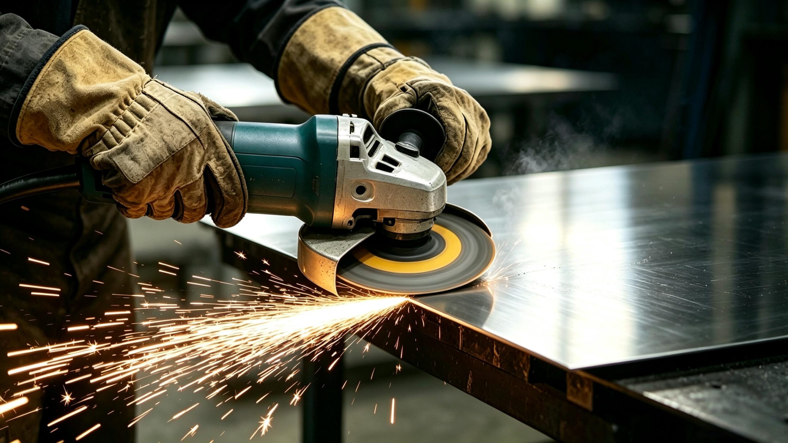
1. Principes techniques fondamentaux et principaux défis liés à la découpe de l'acier inoxydable
En termes simples, la découpe de l'acier inoxydable consiste à séparer le matériau par cisaillement mécanique, fusion par faisceau à haute énergie ou érosion abrasive. Elle constitue une étape essentielle dans le formage de la tôle, l'usinage grossier et les opérations de découpage. En effet, le choix de la méthode de découpe et le réglage des paramètres déterminent directement la qualité des arêtes, la précision dimensionnelle et le coût total de l'opération.
Par rapport à l'acier doux ordinaire, l'acier inoxydable présente une difficulté d'usinage nettement plus élevée. Cette différence s'explique par trois caractéristiques essentielles du matériau :
1.1 Effet de durcissement par déformation important
Tout d'abord, les nuances courantes, telles que l'acier inoxydable austénitique, subissent une déformation plastique superficielle sous l'effet des forces de coupe. Cette déformation augmente rapidement la densité des dislocations et forme une couche durcie par écrouissage nettement plus dure que le matériau de base. En conséquence directe, cette couche durcie accroît la résistance à la coupe et accélère l'usure de l'arête de coupe de l'outil.
1.2 Faible conductivité thermique
De plus, l'acier inoxydable ne conduit la chaleur qu'à hauteur d'environ un tiers de celle de l'acier doux. C'est pourquoi la chaleur générée lors de la découpe ne peut pas se propager rapidement à travers la pièce à usiner et se concentre en grande partie au niveau du tranchant. Cette accumulation de chaleur entraîne facilement une surchauffe et un ramollissement de l'outil, réduit considérablement sa durée de vie et provoque une décoloration par oxydation sur la surface de coupe.
1.3 Haute ténacité et ductilité
Enfin, l'acier inoxydable présente une grande ténacité à la rupture, ce qui fait que les copeaux ne se cassent pas net d'eux-mêmes. Ce phénomène entraîne souvent la formation d'une arête d'accumulation et la déchirure des copeaux pendant l'usinage. À la longue, ces problèmes génèrent davantage de bavures sur l'arête de coupe et détériorent l'état de surface.
2. Procédure opérationnelle standard pour la découpe de l'acier inoxydable
Un processus de travail clair et reproductible est la clé d'une qualité de coupe constante et d'une durée de vie prolongée des outils. Que vous utilisiez des outils manuels ou des machines à commande numérique, le respect de ces sept étapes fondamentales vous garantira des résultats de coupe fiables. Pour plus de clarté, nous les avons réparties en trois phases : la préparation avant la coupe, le contrôle en cours de processus et la finition après la coupe.
Étape 1 : Marquage et traçage précis des cotes
Une bonne précision dimensionnelle commence avant même la première coupe, par un traçage et un marquage minutieux. Pour les travaux de haute précision, utilisez un pointeau en carbure plutôt qu’un marqueur à l’huile afin de tracer des lignes de repère plus fines et plus nettes. Vous devez également vérifier soigneusement les cotes critiques à l'aide d'outils tels que des pieds à coulisse et des jauges de hauteur afin d'éviter tout gaspillage de matière dû à des erreurs de marquage. Pour les séries de production en grande série, en revanche, l'utilisation de gabarits de positionnement ou de montages sur mesure s'avère très efficace pour éliminer les erreurs cumulées liées au marquage manuel.
Étape 2 : Serrage rigide et fixation de la pièce à usiner
Ensuite, fixez solidement la pièce avant de commencer la découpe. L’acier inoxydable est un matériau solide et résistant ; un serrage insuffisant provoquera rapidement des vibrations lors de la découpe, des marques de vibration et peut-être même la rupture des lames. Choisissez une méthode de serrage adaptée à la forme de la pièce. Les tôles fines nécessitent des plaques d’appui rigides pour limiter la déformation pendant la découpe. Les tubes ronds nécessitent un alignement parfait de l'axe par rapport à la direction de découpe afin d'éviter les découpes ovales. Pour les pièces irrégulières, il est préférable d'utiliser un outillage sur mesure afin de maintenir une force de serrage uniforme et d'éviter les points de serrage insuffisants.
Étape 3 : Choix et adaptation des outils et des lames de scie
Choisissez toujours des outils et des lames spécialement conçus pour l’acier inoxydable. Les lames de scie à pointe en carbure ou bimétalliques haute performance sont les plus adaptées, car leur résistance à la chaleur et à l’usure correspond aux propriétés spécifiques de ce matériau. Plus précisément, adaptez le pas des dents (dents par pouce, TPI) à l’épaisseur de votre matériau. Utilisez des lames à denture fine (18 à 24 TPI) pour les tôles de 1,5 mm ou moins d'épaisseur afin d'obtenir des coupes lisses. Utilisez des lames à denture grossière (10 à 14 TPI) pour les matériaux de plus de 5 mm d'épaisseur afin d'améliorer l'évacuation des copeaux et de réduire l'accumulation de chaleur.
Étape 4 : Préréglage et étalonnage des paramètres de découpe
Une fois votre outil choisi, réglez et testez soigneusement vos paramètres de découpe. En règle générale, l’acier inoxydable se découpe mieux à une vitesse comprise entre 50% et 70% de la vitesse de découpe utilisée pour l’acier doux. C’est pourquoi vous devez réduire la vitesse de la machine en fonction de l’épaisseur de votre matériau et du type d’outil utilisé. Avant de lancer la production à plein régime, effectuez une coupe d'essai sur des chutes de matériau afin de vérifier les schémas d'étincelage et la qualité de coupe, puis ajustez les réglages pour obtenir les meilleurs résultats. Réglez votre vitesse d'avance à l'avance afin d'éviter tout changement aléatoire de vitesse en cours de coupe.
Étape 5 : Gestion thermique pendant la découpe
Le contrôle de la température dans la zone de coupe est l'étape la plus importante pour obtenir des résultats constants. Pour obtenir le meilleur résultat possible, utilisez un refroidissement par pulvérisation avec une émulsion ou un fluide de coupe spécialisé, ou éliminez les copeaux à l'aide d'air comprimé afin de réduire la chaleur. En revanche, lors de l'usinage de matériaux épais, adoptez une stratégie d'avance intermittente pour permettre à la chaleur de s'échapper entre les coupes. Ne maintenez jamais l'outil trop longtemps au même endroit, car une surchauffe localisée peut altérer la structure interne du matériau.
Étape 6 : Finition et ébavurage des bords après découpe
Une fois la découpe terminée, passez à la finition des bords et à l'ébavurage. Les bavures et les arêtes vives apparaissent presque toujours après une découpe mécanique et peuvent entraîner des problèmes d'assemblage et des risques pour la sécurité si elles ne sont pas traitées. Utilisez des limes, des outils d'ébavurage rotatifs ou des meules pour lisser les arêtes et éliminer les angles vifs. Si vous constatez une décoloration thermique sur l'arête de coupe, procédez à une passivation par décapage ou à un léger polissage afin de restaurer le film protecteur de l'acier inoxydable et de préserver sa résistance à la corrosion.
Étape 7 : Vérification finale des cotes et de la géométrie
Enfin, vérifiez toutes les pièces finies avant de passer à l'assemblage. Mesurez les cotes clés, notamment la longueur, la rectitude, la perpendicularité et la planéité des arêtes de coupe. Pour les pièces longues et fines, soyez particulièrement attentif à tout gauchissement ou déformation. Détecter rapidement les problèmes dimensionnels permet d'éviter les retouches lors des étapes ultérieures d'assemblage et de soudage, et de réduire les coûts de production globaux.
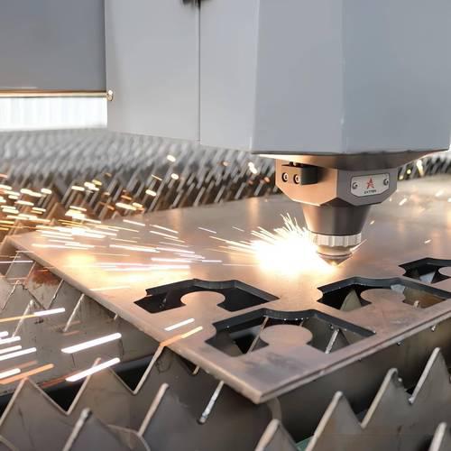
3. Guide comparatif et de sélection des principaux procédés de découpe
3.1 Classification des méthodes de découpe courantes
Les procédés de découpe de l'acier inoxydable peuvent être classés en trois grandes catégories : l'usinage de précision CNC, la découpe thermique industrielle et les outils d'atelier courants. Chaque méthode présente des différences importantes en termes de précision, de vitesse, de coût et d'épaisseur adaptée ; il convient donc d'adapter votre choix à vos besoins de production spécifiques. D'une manière générale, les procédés CNC offrent la plus grande précision, les méthodes thermiques garantissent la plus grande rapidité, tandis que les outils d'atelier offrent la plus grande flexibilité pour les travaux sur site.
3.2 Comparaison des performances selon les indicateurs clés
Le tableau ci-dessous compare huit processus courants selon sept indicateurs de performance clés. Cette comparaison côte à côte vous permet d'évaluer rapidement quelle méthode convient le mieux à votre projet.
| Procédé de découpe | Applications principales | Plage d'épaisseurs | Qualité des bords | Vitesse de traitement | Zone affectée par la chaleur | Coût total |
|---|---|---|---|---|---|---|
| Fraisage CNC | Cavités complexes, usinage de détails de précision | Pièces pleines / pièces structurelles de forme irrégulière | Haute précision, état de surface contrôlable | Modéré | Très faible (coupe contrôlée) | Moyen à élevé |
| Tournage CNC | Arbres, manchons et pièces rotatives | Pièces cylindriques / en forme de barre | Haute précision, excellente concentricité | Haut | Très faible (coupe contrôlée) | Moyen à élevé |
| Découpe au laser | Découpage de précision de tôles fines, contours complexes | Plaques fines à moyennes (jusqu’à environ 30 mm) | Excellent, très peu de bavures, aucune finition secondaire | Haut (automatisé par CNC) | Petit, légèrement plus grand pour les plaques épaisses | Haut |
| Découpage plasma | Découpage rapide de tôles d'épaisseur moyenne | Assiettes d'épaisseur moyenne | Modéré, les bords doivent être nettoyés par la suite | Très élevé | Zone affectée thermiquement (HAZ) importante et profonde pour les matériaux épais | Moyen |
| Découpe au jet d'eau | Plaques épaisses, matériaux thermosensibles | Une gamme complète, allant des tôles fines aux tôles ultra-épaisses | Des bords impeccables, sans aucun dommage thermique | Modéré | Aucun (procédé de travail à froid) | Haut |
| Découpe à la scie circulaire | Atelier de découpage de tôles en ligne droite | Feuilles fines à moyennement épaisses | De belles coupes droites et régulières | Modéré | Petit | Faible |
| Découpe à la scie à ruban | Découpe à longueur fixe de tubes et de barres | Tubes, barres, profilés | Bien, très peu de bavures | Modéré | Très faible | Faible à moyen |
| Découpe à la meuleuse d'angle | Opérations sur site, découpe en petites séries | Matériaux de faible à moyenne épaisseur | Aspect correct, bords irréguliers, ébavurage nécessaire | Relativement rapide (en mode manuel) | Moyen à élevé | Faible |
3.3 Règles pratiques de sélection pour différents scénarios
Principes fondamentaux de sélection : La découpe au laser offre les résultats les plus nets pour les tôles fines nécessitant une grande précision. La découpe au jet d'eau est la solution idéale pour les tôles épaisses qui ne supportent pas la déformation thermique. Les scies à ruban sont les plus performantes pour les travaux de découpe en série de tubes. Les meuleuses d'angle offrent le meilleur compromis entre portabilité et rapidité pour les interventions d'urgence sur site. Enfin, le fraisage CNC offre la plus grande précision pour les pièces complexes et irrégulières nécessitant une grande précision.
4. Stratégies d'optimisation des paramètres clés des processus
Le réglage minutieux des paramètres de votre processus constitue l'un des moyens les plus efficaces d'améliorer l'efficacité de l'usinage et de prolonger la durée de vie des outils. Pour obtenir les meilleurs résultats, vous devez vous concentrer sur quatre aspects essentiels : la vitesse de coupe, le pas des dents, la vitesse d'avance et le refroidissement.
4.1 Réglage dynamique de la vitesse en fonction de l'épaisseur
Commencez par régler la vitesse de coupe en fonction de l'épaisseur du matériau. Un matériau plus épais augmente la surface de contact lors de la coupe et génère davantage de chaleur ; vous devez donc réduire la vitesse de la broche ou de la lame de scie en conséquence. Pour la découpe de tôles épaisses, la combinaison d'une faible vitesse et d'une avance élevée permet d'éviter la surchauffe tout en maintenant un niveau de productivité élevé. En revanche, pour les tôles plus fines, vous pouvez augmenter légèrement la vitesse et l'associer à une lame à denture fine afin d'obtenir une meilleure qualité de coupe.
4.2 Principe d'adaptation entre le pas et l'épaisseur des dents
Deuxièmement, adaptez le pas des dents de votre lame de scie à l'épaisseur du matériau. Le pas des dents influe directement sur la stabilité de la coupe et l'évacuation des copeaux. Les lames à denture fine, avec un nombre de dents par pouce (TPI) élevé, répartissent la force de coupe de manière plus homogène sur les tôles fines, ce qui réduit les déchirures et les bavures. Les lames à denture grossière, avec un TPI faible, laissent davantage d'espace pour les copeaux sur les tôles épaisses, ce qui évite la surchauffe et l'ébréchage de l'outil dû à l'accumulation de copeaux.
4.3 Pression d'alimentation stable et régulable
Troisièmement, maintenez une pression d'avance régulière et contrôlée tout au long de la coupe. Une pression d'avance trop importante accélère l'usure de l'outil et l'accumulation de chaleur, tandis qu'une pression irrégulière provoque un frottement de l'outil contre la pièce et entraîne un durcissement par déformation. C'est pourquoi il convient de maintenir une vitesse d'avance uniforme et continue, et d'éviter de s'arrêter en cours de coupe ou d'effectuer des allers-retours répétés. Ces bonnes pratiques permettent d'éviter de couper à plusieurs reprises la couche superficielle durcie et de retarder la défaillance de l'outil.
4.4 Solutions adaptées de refroidissement et de lubrification
Enfin, utilisez un système de refroidissement et de lubrification adapté à votre opération. Un refroidissement et une lubrification adéquats permettent d’évacuer plus de 60% de chaleur de coupe tout en réduisant le frottement au niveau de l’arête de coupe. L’usinage de finition donne de meilleurs résultats avec une huile de coupe extrême-pression, pour un état de surface plus lisse. L'usinage de dégrossissage se prête bien à l'utilisation d'une émulsion, qui offre un bon compromis entre performances de refroidissement et coût d'exploitation. Si vous travaillez sur site sans système de refroidissement, utilisez de l'air comprimé pour évacuer les copeaux. Cette mesure simple permet de réduire la chaleur et d'empêcher les copeaux de générer une chaleur de frottement supplémentaire.
5. Défauts courants liés à la découpe et solutions
La quasi-totalité des problèmes de qualité liés à l'usinage de l'acier inoxydable provient d'une chaleur non maîtrisée, de paramètres mal adaptés ou d'un mauvais choix d'outils. Vous trouverez ci-dessous les quatre défauts les plus courants, accompagnés de leurs causes profondes et de solutions pratiques que vous pouvez mettre en œuvre immédiatement.
5.1 Rééducation fonctionnelle intensive
Causes : Interrompre l'avance en cours de coupe, utiliser des outils usés ou travailler à une vitesse trop élevée, ce qui provoque des frottements répétés à la surface.
Solutions : Veillez à ce que le mouvement d'avance reste régulier et continu tout au long de la coupe. Inspectez régulièrement les arêtes de l'outil et remplacez-les immédiatement dès que l'usure dépasse la limite acceptable. Réduisez la vitesse de coupe et utilisez une quantité suffisante de liquide de refroidissement afin de limiter la déformation plastique à la surface du matériau.
5.2 Oxydation et décoloration des bords de coupe
Causes : Une chaleur excessive dans la zone de découpe provoque l'oxydation du chrome présent à la surface de l'acier inoxydable. Cette oxydation se manifeste généralement par des traces bleues, jaunes ou brunes et réduit la résistance à la corrosion du matériau.
Solutions : Réduisez la vitesse de l'équipement et augmentez la vitesse d'avance afin de réduire la durée d'exposition à la chaleur. Augmentez la pulvérisation de liquide de coupe ou utilisez davantage d'air comprimé pour évacuer la chaleur plus rapidement. Pour les pièces présentant déjà une décoloration, vous pouvez recourir à la passivation ou au polissage afin d'éliminer les traces et de rétablir une résistance totale à la corrosion.
5.3 Présence excessive de bavures sur les arêtes de coupe
Causes : Des lames de scie très usées, un pas de denture inadapté à l'épaisseur du matériau, un serrage insuffisant de la pièce à usiner ou une vitesse d'avance trop élevée.
Solutions : Installez une nouvelle lame de scie spécialement conçue pour l'acier inoxydable dès les premiers signes d'usure. Adaptez le nombre de dents par pouce (TPI) de votre outil à l'épaisseur de votre tôle pour obtenir des coupes nettes et lisses. Serrez bien la pièce à usiner afin d'éliminer les vibrations pendant la coupe. Réglez soigneusement la vitesse d'avance pour vous assurer que les copeaux se cassent proprement et de manière régulière.
5.4 Déformation et gauchissement des tôles minces
Causes : Une répartition inégale de la chaleur pendant la découpe entraîne une dilatation et une contraction thermiques irrégulières sur l'ensemble de la tôle. Les tôles minces manquent en outre de soutien structurel, de sorte que la force de découpe peut facilement provoquer une déformation plastique permanente.
Solutions : Placez des plaques d'appui rigides sous les tôles fines et serrez-les en plusieurs points pour assurer un soutien uniforme. Réduisez l'apport de chaleur en utilisant un avancement rapide à grande vitesse ou des méthodes de découpe à froid. Pour les tôles longues et de grande taille, utilisez quant à vous des trajectoires de découpe symétriques afin de limiter l'accumulation de contraintes.
6. Solutions d'usinage pour différents types de pièces
Les différentes formes de pièces nécessitent des approches d'usinage différentes. Vous trouverez ci-dessous des recommandations spécifiques pour trois types de pièces courants que vous rencontrerez dans votre travail quotidien.
6.1 Pièces en tôle
La découpe au laser ou à la scie circulaire offre une excellente qualité des bords avec une déformation minimale pour les tôles fines de moins de 3 mm. Pour les tôles d'épaisseur moyenne, comprises entre 3 mm et 20 mm, optez pour la découpe au laser ou au plasma en fonction de vos exigences de précision. La découpe au plasma ou au jet d'eau est la plus adaptée aux tôles de plus de 20 mm, car elle offre un bon compromis entre vitesse d'usinage et qualité des bords finis.
6.2 Pièces tubulaires et barres
Les coupe-tubes à rouleaux sont particulièrement adaptés aux tubes en acier inoxydable à paroi mince, car ils permettent d'obtenir des coupes nettes et sans bavures avec un minimum d'effort supplémentaire. La découpe à la scie à ruban offre une excellente rectitude de coupe et un rendement constant pour les tubes à paroi épaisse, les tuyaux de grand diamètre et les barres pleines. Le tournage CNC permet d'effectuer à la fois la découpe et l'usinage du diamètre extérieur en une seule opération pour les pièces d'arbres de haute précision.
6.3 Opérations manuelles et sur site
Les cisailles d'aviation permettent de cisailler efficacement les tôles fines pour les petits lots et les travaux d'entretien sur site. Pour les tôles et les tubes d'épaisseur moyenne, les meuleuses d'angle équipées de disques de coupe spécifiques à l'acier inoxydable offrent des performances fiables. Lorsque vous n'avez besoin que de coupes grossières ne nécessitant pas une grande précision, une scie à métaux standard constitue un choix économique. Portez toujours une protection complète pour les yeux et les mains lors des opérations manuelles afin d'éviter les brûlures causées par les copeaux chauds.
7. Foire aux questions techniques
7.1 Notions fondamentales sur les matériaux et les procédés
L'acier inoxydable est-il plus difficile à découper que l'acier doux ?
Oui, c'est le cas. Cette difficulté accrue s'explique par deux facteurs clés. Premièrement, l'acier inoxydable subit un durcissement par déformation beaucoup plus rapide que l'acier doux, ce qui fait que la dureté de surface au niveau de la coupe augmente rapidement et accélère l'usure de l'outil. D'autre part, l'acier inoxydable est un mauvais conducteur de chaleur ; la chaleur s'accumule donc dans la zone de coupe, ce qui provoque facilement un ramollissement de l'outil et une défaillance prématurée. À conditions d'usinage identiques, la durée de vie des outils est environ 1/3 à 1/2 moins longue lors de l'usinage de l'acier inoxydable que lors de celui de l'acier doux.
Quels sont les principaux éléments à prendre en compte pour la découpe de l'acier inoxydable 304 ?
Le 304 est la nuance d'acier inoxydable austénitique la plus répandue sur le marché. Pour l'usiner, utilisez toujours d'abord des outils en carbure ou bimétalliques, et réglez la vitesse de coupe à environ 60% de celle que vous utiliseriez pour de l'acier au carbone ordinaire. Maintenez une avance régulière tout au long de la coupe et évitez de marquer une pause en cours de coupe, ce qui provoque un écrouissage. Pour obtenir les meilleurs résultats, utilisez un refroidissement par émulsion afin d'améliorer l'état de surface et de prolonger la durée de vie de l'outil.
Quelle est la meilleure méthode pour découper des tôles épaisses en acier inoxydable ?
La méthode la plus adaptée dépend de vos exigences en matière de qualité. Pour les projets nécessitant une grande précision et l'absence totale de dommages thermiques sur les bords, la découpe au jet d'eau à froid s'impose comme le choix idéal. Si vous privilégiez une découpe rapide et que vous acceptez une précision modérée au niveau des bords, la découpe au plasma répondra au mieux à vos besoins. Lorsque vous disposez d’un équipement à haute puissance, la découpe au laser à fibre optique offre également d’excellents résultats pour les tôles d’une épaisseur allant jusqu’à 25 mm.
7.2 Conseils pratiques d'utilisation et de bricolage
Les lames de scie à bois classiques permettent-elles de couper de l'acier inoxydable ?
Absolument pas — n’utilisez jamais une lame de scie à bois pour couper de l’acier inoxydable. Les lames destinées au travail du bois présentent des niveaux de dureté et des géométries de dents conçus exclusivement pour le bois. Leur utilisation sur de l’acier inoxydable entraînera une usure rapide de la lame, l’ébréchage des dents, voire une rupture complète, ce qui peut, dans les cas les plus graves, causer des blessures graves à l’opérateur. Pour couper de l'acier inoxydable, utilisez toujours une lame de scie en carbure spécialisée, réduisez la vitesse de l'équipement, fixez solidement la pièce à usiner et respectez toutes les consignes de sécurité.
Comment découper une tôle d'acier inoxydable chez soi ?
Pour les petites tôles fines en acier inoxydable utilisées dans le cadre de projets de bricolage, une meuleuse d'angle équipée d'un disque de coupe pour acier inoxydable constitue une solution polyvalente et économique. Pour les tôles ultra-fines d'une épaisseur inférieure à 0,5 mm, vous pouvez également utiliser des cisailles industrielles d'aviation pour le cisaillage manuel. Quel que soit l'outil utilisé, portez toujours des lunettes de sécurité et des gants de protection, et éloignez les matériaux inflammables et explosifs de la zone de travail.
Conclusion
En résumé, l'usinage de l'acier inoxydable est un processus systématique qui repose sur un contrôle équilibré des paramètres et sur des procédures opérationnelles normalisées. Le choix du procédé approprié, le réglage correct des paramètres et le respect des procédures standard : tous ces facteurs contribuent ensemble à obtenir des résultats d'usinage de haute qualité et à haut rendement.
PartsMastery exploite un système complet d'usinage CNC offrant des capacités éprouvées en matière d'usinage de l'acier inoxydable. Nous proposons des services d'alésage, de perçage et d'usinage de formes complexes de haute précision, avec des tolérances dimensionnelles pouvant descendre jusqu'à ±0,005 mm. Tous les processus font appel à un contrôle CNC en boucle fermée et à une surveillance de la qualité en temps réel afin de garantir la cohérence dimensionnelle de chaque pièce.
Du prototypage rapide à la production en série stable, PartsMastery propose des solutions fiables de fabrication métallique pour les secteurs haut de gamme, notamment l'aérospatiale, les dispositifs médicaux et l'industrie automobile. Nos procédés répondent à des exigences strictes en matière de performances et de précision, même dans les conditions de travail les plus exigeantes.