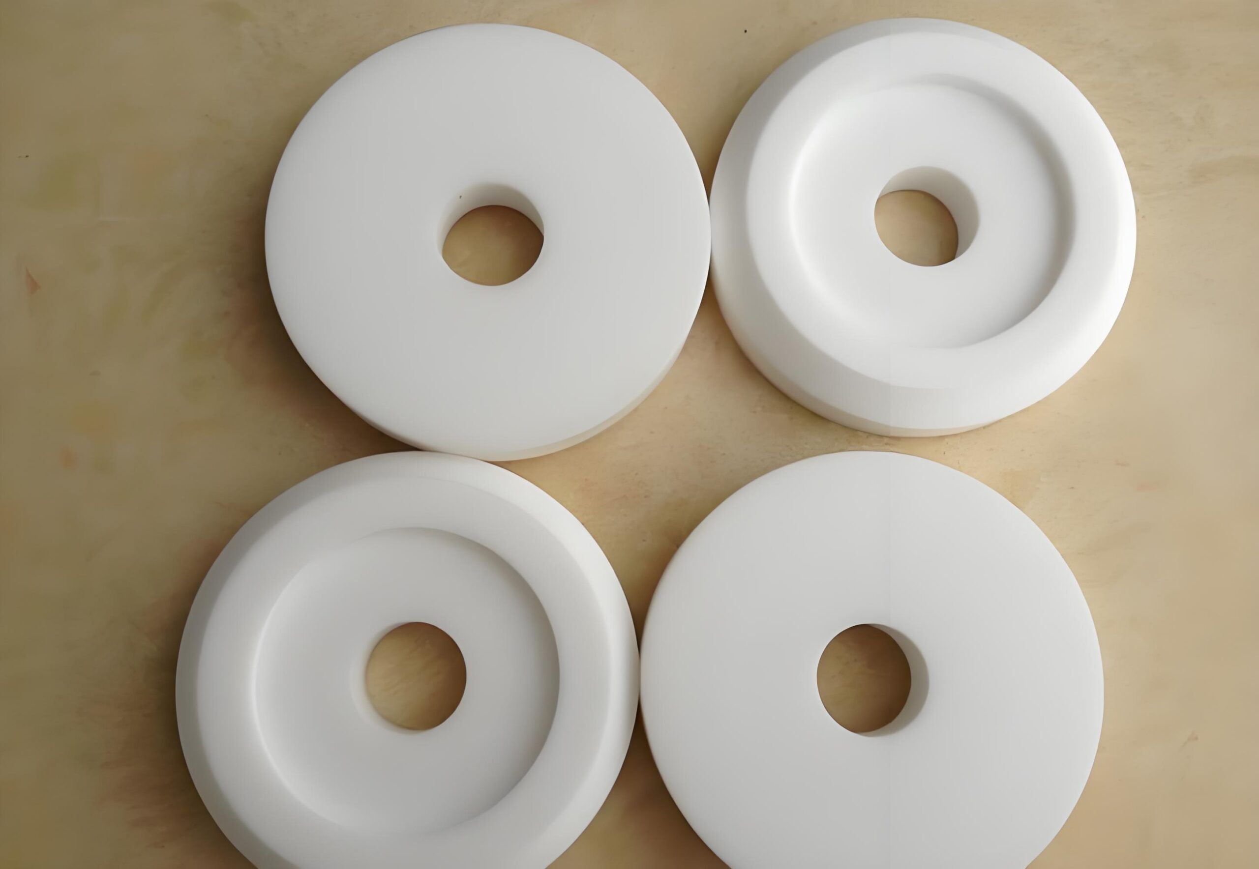
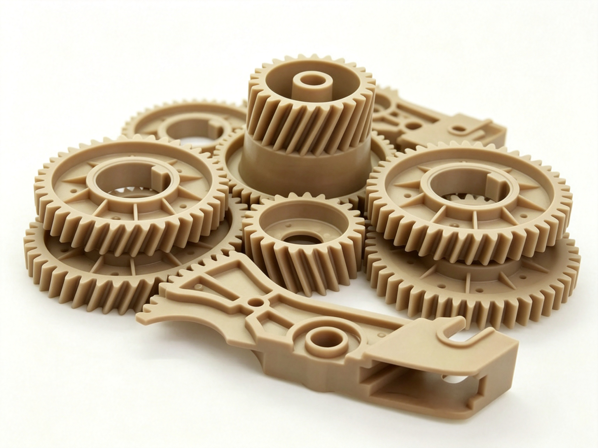
In demanding engineering environments, the material choice between PEEK and PTFE directly impacts equipment reliability. These environments include aerospace, oil and gas, semiconductor manufacturing, medical devices, and industrial machinery. Consequently, PEEK stands out as the preferred high-performance plastic for structural components. It delivers exceptional mechanical strength, stiffness, wear resistance, and dimensional stability. Meanwhile, PTFE occupies an irreplaceable position in corrosion-resistant and low-friction applications. Its near-perfect chemical inertness, low friction coefficient, and sealing performance make it unique.
However, simply assuming that “PEEK is always better because it is stronger” represents a one-sided view. The same applies to thinking “PTFE is universally superior because it resists chemicals.” Therefore, correct material selection requires a deep understanding of the molecular structural differences between the two materials. Engineers must also evaluate operating temperature, mechanical load, chemical environment, and friction conditions. Furthermore, dimensional accuracy requirements and total lifecycle cost matter too. This guide starts from the molecular structure level. It systematically compares core properties, CNC machining characteristics, typical applications, and cost-effectiveness. Ultimately, the goal is to provide engineers with an actionable material selection decision framework.
1. Deep Dive into PEEK Material
.1 Molecular Structure and Basic Properties
Polyether ether ketone (PEEK) is a semi-crystalline high-performance thermoplastic. Its molecular backbone forms through a nucleophilic substitution reaction. The reactants are hydroquinone and 4,4′-difluorobenzophenone. Specifically, ether bonds (-O-) and ketone groups (-CO-) alternate along the chain and connect to benzene rings. This creates a molecular structure that balances rigidity and flexibility perfectly. For instance, the ether bonds provide chain flexibility and processing flowability. In contrast, the ketone groups and benzene rings deliver high rigidity, high strength, and excellent thermal stability.
PEEK exhibits a glass transition temperature (Tg) of approximately 143°C. Its melting point sits around 343°C. Furthermore, crystallinity typically ranges from 30% to 35%, and annealing treatment can push it above 40%. With a density of 1.30–1.32 g/cm³, PEEK weighs only about one-sixth of steel. Yet its specific strength and specific stiffness approach those of certain metal alloys. Additionally, PEEK delivers outstanding flame retardancy. It achieves a UL 94 V-0 rating with an oxygen index of 35% at 1.45 mm thickness. As a result, its low smoke density and low toxicity meet the strict fire safety requirements of aerospace and rail transit.
1.2 Core Performance Advantages
PEEK’s core advantages concentrate in four dimensions. First, it delivers exceptional mechanical properties. The tensile strength reaches 90–100 MPa. Meanwhile, the tensile modulus reaches 3.6–4.0 GPa. Flexural strength reaches 140–170 MPa. Below 200°C, PEEK maintains a high retention rate of its room-temperature mechanical properties.
Second, it offers outstanding heat resistance. PEEK can operate short-term at 260°C and long-term at 200°C without significant performance degradation. Its heat deflection temperature (HDT @ 1.82 MPa) reaches 160°C. Furthermore, glass fiber or carbon fiber reinforcement can push it above 300°C.
Third, PEEK provides excellent wear resistance and creep resistance. Under dry friction conditions, it achieves a relatively low friction coefficient of 0.30–0.35. Filling with PTFE, graphite, or carbon fiber can reduce the friction coefficient below 0.15. Additionally, its creep resistance ranks among the best in engineering plastics. At 150°C and 20 MPa stress, the 1000-hour creep strain measures only 2%–3%.
Fourth, PEEK demonstrates good chemical resistance. It tolerates most organic acids, inorganic acids, alkalis, salt solutions, oils, fuels, and hydrocarbons. However, only concentrated sulfuric acid, concentrated nitric acid, halogenated hydrocarbons, and certain polar solvents can attack it.
1.3 Limitations and Processing Requirements
The main limitation of PEEK lies in its higher cost. Raw material prices typically run 3–5 times those of PTFE. Additionally, PEEK requires high processing temperatures. Injection barrel temperature reaches 360–400°C, and mold temperature reaches 170–200°C. Consequently, this demands high heating capacity and precise temperature control from the equipment. PEEK is also moisture-sensitive, so strict drying must precede processing. The recommended drying condition is 150°C for 3–4 hours. Otherwise, silver streaks, bubbles, or reduced mechanical properties may appear. Although PEEK’s chemical resistance is good, it does not match the breadth of PTFE. In fact, certain strong oxidizing acids and halogenated hydrocarbons can attack it.
2. Deep Dive into PTFE Material
2.1 Molecular Structure and Basic Properties
Polytetrafluoroethylene (PTFE) is a fluoropolymer. It is produced through free-radical polymerization of tetrafluoroethylene monomers. Specifically, its molecular backbone consists of carbon-carbon single bonds. Both hydrogen atoms on each carbon atom are fully replaced by fluorine atoms. This forms a highly symmetrical helical molecular structure. Fluorine has an extremely high electronegativity of 4.0. Moreover, the C-F bond energy reaches 485 kJ/mol, one of the strongest chemical bonds known. As a result, this structural feature gives PTFE exceptionally high chemical stability and thermal stability.
PTFE has a density of 2.15–2.20 g/cm³, making it one of the densest plastics. Its glass transition temperatures occur around -127°C and 19°C (two secondary transitions). The melting point sits around 327°C. Furthermore, crystallinity typically ranges from 50% to 75%. PTFE possesses an extremely low surface energy of 18.5 mN/m. This ranks among the lowest for known solid materials. Consequently, this property delivers excellent non-stick and self-lubricating characteristics. Its friction coefficient drops as low as 0.04–0.10, ranking among the lowest for any known solid material.
2.2 Core Performance Advantages
PTFE’s core advantages concentrate in four dimensions. First, it offers near-perfect chemical inertness. PTFE resists attack from virtually every known chemical. This includes strong acids, strong alkalis, strong oxidizers, organic solvents, halogens, and aqua regia. However, only molten alkali metals, fluorine gas, and certain fluorine-containing compounds can attack it. These attacks require high temperature and pressure. Therefore, this makes PTFE the material of choice for chemical processing, semiconductor wet processing, and high-purity fluid handling.
Second, PTFE delivers an extremely low friction coefficient and excellent non-stick properties. Its friction coefficient reaches as low as 0.04–0.10. It maintains this low value even under unlubricated conditions. Consequently, this makes it an ideal self-lubricating material. Its extremely low surface energy means almost no substance can adhere to its surface. This explains its widespread use in non-stick coatings, food processing, and release agents.
Third, PTFE offers a broad temperature range. It operates long-term from -200°C to +260°C and short-term up to 300°C. This gives it one of the widest temperature ranges among plastics. Fourth, PTFE provides excellent electrical insulation. Its dielectric constant drops as low as 2.1, and dielectric loss as low as 0.0002. Both remain stable across a wide frequency and temperature range. As a result, this makes it an ideal high-frequency insulation material.
2.3 Limitations and Processing Requirements
The main limitations of PTFE lie in its low mechanical strength and poor creep resistance. Tensile strength measures only 20–35 MPa. The tensile modulus measures only 0.4–0.6 GPa. Both values are far below those of PEEK. Under sustained load, PTFE easily undergoes creep or cold flow. Consequently, this limits its use in structural load-bearing components. Additionally, pure PTFE exhibits poor wear resistance and wears quickly under heavy load. Fillers such as glass fiber, carbon fiber, graphite, bronze, or molybdenum disulfide typically improve its wear performance.
PTFE also presents greater processing difficulty. Because its melt viscosity is extremely high (10^10–10^12 Pa·s), it does not flow even above its melting point. Conventional injection molding, extrusion, or blow molding cannot process it. Instead, manufacturers typically use a cold-press forming plus high-temperature sintering process. This process resembles powder metallurgy. During CNC machining, PTFE’s softness, flexibility, and clamping sensitivity cause elastic deformation. This makes tight tolerance control challenging. Furthermore, PTFE has a large coefficient of linear thermal expansion of 10–12×10^-5/°C. This is more than 10 times that of steel, so dimensional fluctuations become significant with temperature changes.
3. Quantitative Comparison Across Ten Key Dimensions
To present the performance differences between the two materials more clearly, the following table provides a quantitative comparison across ten key engineering dimensions. All data come from typical material datasheets provided by manufacturers. However, actual values may vary depending on the specific grade, filler modification, and testing standard.
Comparison Dimension
PEEK (Polyether Ether Ketone)
PTFE (Polytetrafluoroethylene)
Density (g/cm³)
1.30–1.32
2.15–2.20
Glass Transition Tg (°C)
~143
-127 / 19
Melting Point (°C)
~343
~327
Long-Term Use Temp (°C)
200
260
Tensile Strength (MPa)
90–100
20–35
Tensile Modulus (GPa)
3.6–4.0
0.4–0.6
Coefficient of Friction
0.30–0.35 (neat) / 0.15 (filled)
0.04–0.10
Chemical Resistance
Good (not resistant to strong oxidizing acids and halogenated hydrocarbons)
Excellent (resists almost all chemicals)
Creep Resistance
Excellent
Poor (prone to cold flow)
Raw Material Cost (relative)
3–5×
1× (baseline)
4. In-Depth Analysis of Core Differences
4.1 Mechanical Strength and Stiffness
Mechanical strength and stiffness represent the most significant performance difference between PEEK and PTFE. PEEK achieves a tensile strength of 90–100 MPa. This is 3–5 times that of PTFE (20–35 MPa). Meanwhile, its tensile modulus reaches 3.6–4.0 GPa. This is 6–10 times that of PTFE (0.4–0.6 GPa). Consequently, these values mean PEEK can withstand significantly higher tensile, bending, and compressive loads. Its deformation under load remains far smaller than that of PTFE. With carbon fiber reinforcement, PEEK’s tensile modulus can rise to 18–20 GPa. This approaches aluminum alloy levels and makes it an ideal material for metal replacement.
PTFE’s low strength and low stiffness are not shortcomings. Instead, they are inherent characteristics of its molecular structure. In sealing applications, PTFE’s softness and flexibility allow it to conform better to sealing surfaces. It fills microscopic irregularities and achieves excellent sealing performance. In low-friction sliding applications, PTFE’s low modulus enables elastic deformation. This increases the actual contact area, thereby reducing contact stress and friction coefficient. Consequently, PTFE suits seals, gaskets, liners, and low-friction sliding components. PEEK, by contrast, suits load-bearing parts such as bearings, gears, valve seats, and brackets.
4.2 Heat Resistance and Load Thermal Stability
Both PEEK and PTFE offer excellent heat resistance, but their high-temperature performance differs fundamentally. PTFE operates long-term at 260°C and short-term at 300°C. It maintains chemical stability and low-friction performance across a wide temperature range from -200°C to +260°C. However, PTFE’s mechanical strength and creep resistance decline significantly at elevated temperatures. It deforms easily under load. Therefore, PTFE suits high-temperature sealing, insulation, and chemical resistance applications. It does not fit structural load-bearing parts at high temperature.
PEEK’s long-term use temperature reaches 200°C, lower than PTFE. Yet its mechanical strength retention at high temperature far exceeds that of PTFE. At 200°C, PEEK still retains approximately 50% of its room-temperature tensile strength and stiffness. Its excellent creep resistance allows it to maintain dimensional stability and structural integrity under high-temperature, high-load conditions. Furthermore, with glass fiber or carbon fiber reinforcement, PEEK’s heat deflection temperature can rise above 300°C. Its long-term use temperature can reach 250°C. Therefore, for parts that must withstand both high temperature and mechanical load, PEEK usually represents the more reliable choice. Examples include high-temperature bearings, valve seats, and support components.
4.3 Friction and Wear Performance
Friction and wear performance represent one of the most distinctive differences in the PEEK versus PTFE comparison. PTFE achieves one of the lowest friction coefficients among known solid materials (0.04–0.10). It performs especially well under unlubricated, low-speed, light-load conditions. Its low-friction characteristic stems from the highly symmetrical helical structure of its molecular chains. Its extremely low surface energy also plays a role. During friction, PTFE molecular chains slide easily relative to each other. They form a transfer film on the mating surface, achieving a self-lubricating effect. For this reason, PTFE finds wide use in low-load bearings, bushings, sliding plates, guide rails, and non-stick surfaces.
PEEK’s friction coefficient (0.30–0.35) exceeds that of PTFE. But its wear resistance far surpasses that of pure PTFE, especially under high load, high speed, and high temperature. PEEK’s high rigidity and high strength prevent plastic deformation and adhesive wear during friction. Its wear rate measures only 1/10 to 1/5 that of pure PTFE. Filling with PTFE, graphite, or carbon fiber can reduce PEEK’s friction coefficient below 0.15. It also maintains excellent wear resistance. Consequently, this makes PEEK an ideal material for high-performance bearings, gears, and sliding components. Therefore, for low-load, low-speed applications requiring extremely low friction, PTFE fits better. For high-load, high-speed applications requiring long service life and high wear resistance, PEEK performs better.
4.4 Chemical Resistance
Chemical resistance stands as PTFE’s most advantageous performance area. The C-F bond energy in PTFE reaches 485 kJ/mol. Its molecular chains are highly symmetrical with no reactive groups. This makes PTFE virtually immune to attack from every known chemical. PTFE tolerates concentrated sulfuric acid, concentrated nitric acid, concentrated hydrochloric acid, aqua regia, and hydrofluoric acid. It also resists strong alkalis, organic solvents, halogens, oxidizers, and reducing agents. However, only molten alkali metals, fluorine gas, and certain fluorine-containing compounds can attack it. These attacks require high temperature and pressure. Therefore, this makes PTFE the material of choice for chemical processing, semiconductor wet processing, high-purity fluid handling, and corrosion-resistant sealing.
Although PEEK demonstrates good chemical resistance, it does not match the breadth of PTFE. PEEK tolerates most organic acids, inorganic acids, alkalis, salt solutions, oils, fuels, hydrocarbons, and steam. However, concentrated sulfuric acid, concentrated nitric acid, halogenated hydrocarbons, phenol, and certain polar solvents can attack or swell it. PEEK’s advantage lies in the fact that, within its chemical resistance range, it simultaneously maintains excellent mechanical strength and dimensional stability. PTFE, while offering broader chemical resistance, exhibits low mechanical strength and tends to creep in corrosive environments. Consequently, for sealing and lining applications that require only chemical resistance, PTFE fits better. For structural parts that require both chemical resistance and mechanical load-bearing capacity, PEEK performs better.
4.5 Dimensional Stability and Creep Resistance
Dimensional stability and creep resistance represent critical factors affecting the assembly performance and long-term reliability of precision parts. PEEK delivers excellent dimensional stability and creep resistance. Its molding shrinkage measures only 0.5%–1.0% with low anisotropy. Its coefficient of linear thermal expansion reaches 4.5–5.5×10^-5/°C. This approaches aluminum alloy levels. At 150°C and 20 MPa stress, the 1000-hour creep strain measures only 2%–3%. Consequently, these properties allow PEEK to maintain precise dimensions and shape under load, temperature changes, and processing stress. This makes it suitable for precision mechanical parts, semiconductor components, medical devices, and high-performance assemblies.
PTFE exhibits poorer dimensional stability and creep resistance. Its molding shrinkage reaches 3%–5% with significant anisotropy. Its coefficient of linear thermal expansion reaches 10–12×10^-5/°C. This is more than 10 times that of steel. Under sustained load, PTFE easily undergoes creep or cold flow. At room temperature and 10 MPa stress, the 1000-hour creep strain can reach 10%–20%. Consequently, these characteristics mean PTFE parts experience significant dimensional fluctuations with temperature changes and sustained load. They become unsuitable for precision-fitted structural parts. However, in sealing applications, PTFE’s controllable deformation and creep actually prove beneficial. They allow the seal to conform better to the sealing surface. They compensate for wear and surface irregularities, achieving long-term reliable sealing. Therefore, for precision structural parts, PEEK remains the first choice. For seals and gaskets, PTFE’s controllable deformation characteristic becomes an advantage.
5. CNC Machining Strategy Comparison
Both PEEK and PTFE can manufacture custom parts through CNC machining. But due to differences in mechanical and thermal properties, their machining strategies and process parameters differ significantly. The correct machining strategy affects not only production efficiency and tool life. It also directly determines the dimensional accuracy and surface quality of the finished parts.
5.1 PEEK Machining Key Points
PEEK offers good rigidity and high strength. Its cutting performance resembles that of hard wood or light metals. It can achieve high dimensional accuracy and surface finish. When machining PEEK, manufacturers recommend sharp carbide or diamond tools. Large rake and relief angles reduce cutting resistance and frictional heat. Cutting speed should stay within 100–300 m/min. Feed rate should stay at 0.05–0.15 mm/tooth. Furthermore, cutting depth should be 1–3 mm for roughing or 0.1–0.5 mm for finishing.
The key control points in PEEK machining lie in thermal management and internal stress control. Although PEEK offers excellent heat resistance, excessive local temperature during cutting can still cause material softening, surface burning, or increased internal stress. Therefore, manufacturers recommend air cooling or compressed air cooling. They avoid using large amounts of coolant that could cause thermal shock. Additionally, PEEK tends to generate internal stress during machining. For high-precision parts or parts with large material removal, annealing treatment after roughing can eliminate internal stress before finishing. The recommended annealing condition is 200°C for 2–4 hours. Consequently, PEEK can stably achieve dimensional tolerances of ±0.02–0.05 mm. It can also achieve surface finishes of Ra 0.4–0.8 µm. This makes it an ideal high-performance plastic for precision CNC machining.
5.2 PTFE Machining Key Points
PTFE exhibits low rigidity and good flexibility. It easily undergoes elastic deformation under tool pressure during cutting. This causes a “tool deflection” phenomenon that affects dimensional accuracy and geometric tolerances. When machining PTFE, manufacturers recommend sharp high-speed steel or carbide tools. Large rake and relief angle geometries minimize cutting forces. Cutting speed can increase appropriately to 200–500 m/min. But feed rate should stay small at 0.05–0.1 mm/tooth. Moreover, cutting depth should remain shallow at 0.5–2 mm. This avoids material being squeezed, torn, or producing burrs.
The main challenges in PTFE machining include clamping deformation, burr control, and dimensional springback. Because PTFE is soft and flexible, traditional three-jaw chucks or vises can easily deform the part. After release, dimensional springback affects machining accuracy. Therefore, manufacturers recommend vacuum fixtures, soft jaws, mandrel support, or dedicated tooling for multi-point uniform clamping. This reduces clamping deformation. PTFE’s high toughness causes continuous ribbon chips and edge burrs during cutting. This is especially true at hole exits and contour edges. Keeping tools sharp, using climb milling, and adding support or relief grooves at exits help. PTFE tolerances typically measure ±0.05–0.1 mm. For thin walls, long parts, small holes, and tight-fitting structures, tolerance control becomes more difficult. Consequently, designers should预留 reasonable tolerance compensation space.
5.3 Tolerance, Surface Finish, and Deformation Control
In tolerance control, PEEK clearly outperforms PTFE. PEEK’s high rigidity and low creep allow it to stably achieve dimensional tolerances of ±0.02–0.05 mm. For simple geometries it can even reach ±0.01 mm. PTFE tolerances typically measure ±0.05–0.1 mm. They are more affected by temperature, clamping force, and internal stress. Batch consistency is not as good as PEEK. Therefore, for structural parts requiring precision fitting, sealing, or assembly, PEEK’s machining advantage becomes more apparent.
In surface finish, PEEK can achieve Ra 0.4–0.8 µm in finishing. Polishing can produce a mirror finish below Ra 0.1 µm. PTFE surface finish typically measures Ra 1.6–3.2 µm. Although its surface inherently offers low friction and non-stick characteristics, polishing and fine surface treatment remain difficult due to the material’s softness. In deformation control, PEEK’s low molding shrinkage, small thermal expansion coefficient, and good creep resistance give it excellent post-machining dimensional stability. PTFE’s high molding shrinkage, large thermal expansion coefficient, and poor creep resistance cause significant dimensional fluctuations after machining and with temperature changes. Consequently, for parts requiring high precision and high consistency, PEEK represents the more reliable choice. For seals, gaskets, and low-friction components, PTFE’s controllable deformation characteristic actually proves beneficial.
6. Typical Application Fields
6.1 Aerospace
In the aerospace field, PEEK finds wide use in manufacturing lightweight structural parts, brackets, fasteners, bushings, bearings, and gears. It also suits other components requiring high strength-to-weight ratios. Its excellent stiffness, temperature stability, and flame retardancy make it suitable for demanding aerospace assembly environments. It achieves a UL 94 V-0 rating with low smoke and low toxicity. Furthermore, carbon fiber reinforced PEEK offers specific strength approaching aluminum alloy at only half the density. This delivers significant lightweighting advantages in aircraft interiors, structural parts, and engine components.
PTFE in aerospace mainly manufactures low-friction bearings, seals, cable insulation, and chemical-resistant components. In applications where low friction, electrical insulation, or fluid resistance matters more than structural strength, PTFE works very well. Examples include seals in aircraft hydraulic systems, gaskets in fuel systems, cable insulation layers, and bearing bushings in sliding mechanisms.
6.2 Oil and Gas
In oil and gas applications, PEEK commonly manufactures backup rings, valve components, anti-extrusion parts, compressor components, and high-pressure parts. It offers excellent load resistance and deformation resistance. Its dimensional stability becomes especially important in pressure systems. It maintains seal clearances and fitting precision in high-temperature, high-pressure downhole environments. Additionally, PEEK demonstrates good resistance to crude oil, natural gas, and drilling fluids. This makes it an ideal material for downhole tools and wellhead equipment.
PTFE finds wide application in seals, gaskets, valve seats, and chemical-resistant components. In applications where corrosion resistance and sealing performance represent the primary requirements, PTFE performs especially well when properly designed. Examples include valve seats in wellhead valves, gaskets in pipeline flanges, seal rings in chemical pumps, and corrosion-resistant liners. Furthermore, glass fiber or carbon fiber filled PTFE can improve wear resistance and creep resistance. This suits higher pressure and temperature conditions.
6.3 Semiconductor
In semiconductor applications, PTFE suits high-purity chemical handling, tubing, fittings, and components exposed to corrosive wet process chemicals. Its chemical inertness helps reduce contamination and degradation risks. It ensures high chemical purity. Additionally, PTFE offers excellent non-stick and low-friction characteristics. It suits wafer handling, chemical delivery, and sealing and lining in wet process equipment.
PEEK commonly manufactures wafer handling components, test sockets, fixtures, and precision tools. These applications demand high strength, dimensional stability, and wear resistance. When components must maintain precise geometry, PEEK usually represents the first-choice material. Furthermore, PEEK demonstrates good resistance to plasma etching and chemicals. It suits structural and moving parts in semiconductor manufacturing equipment.
6.4 Medical Devices
In the medical device field, PEEK finds wide application due to its excellent biocompatibility, sterilization resistance, and mechanical properties. PEEK tolerates repeated autoclave sterilization at 134°C. It also tolerates ethylene oxide sterilization and gamma ray sterilization. It maintains stable mechanical properties and dimensional accuracy after sterilization cycles. Its elastic modulus approaches that of human cortical bone. This reduces the stress shielding effect. Consequently, it makes PEEK an ideal material for orthopedic implants such as spinal fusion cages, bone screws, and bone plates. Additionally, PEEK finds wide use in surgical instruments, dental equipment, rehabilitation devices, and diagnostic equipment components.
PTFE in medical devices mainly manufactures seals, gaskets, catheters, guidewire coatings, and non-stick surfaces. Its excellent chemical inertness and biocompatibility make it suitable for implants and components that contact human tissue. PTFE’s low-friction characteristic makes it an ideal material for guidewire coatings and catheter liners. It reduces frictional resistance during insertion. Furthermore, expanded PTFE (ePTFE) also finds wide use in artificial blood vessels, cardiac patches, and soft tissue repair materials.
6.5 Industrial Equipment
In industrial equipment, PEEK manufactures pump components, wear rings, bushings, bearings, gears, valve seats, and load-bearing plastic parts. It helps reduce weight while maintaining mechanical reliability. PEEK’s high wear resistance and low-friction characteristics suit high-speed moving parts. They reduce lubrication requirements and maintenance costs. In food processing and pharmaceutical equipment, PEEK’s cleanability and sterilization resistance make it an ideal material for parts that contact food and pharmaceuticals.
PTFE finds wide application in liners, seals, gaskets, sliding surfaces, insulation components, and low-friction assemblies. It helps reduce adhesion, chemical corrosion, and frictional wear in many industrial systems. PTFE’s non-stick characteristic suits conveyor belts, molds, and baking pan coatings in food processing equipment. Additionally, its excellent electrical insulation properties suit high-voltage cable insulation, electronic component encapsulation, and high-frequency communication equipment.
7. Cost-Effectiveness Analysis
Cost represents a critical factor that cannot be ignored in material selection decisions. PEEK raw material costs typically run 3–5 times those of PTFE. Its high processing temperatures and strict equipment requirements also make processing costs higher than PTFE. For applications that require only chemical resistance, sealing, or low-friction performance, PTFE offers a clear cost advantage. It delivers excellent performance at lower material cost.
However, from a total lifecycle cost (LCC) perspective, PEEK’s higher cost may be offset by longer service life, lower replacement frequency, and lower maintenance costs. For example, in high-load bearing applications, PEEK bearings may last 5–10 times longer than filled PTFE bearings. They resist creep and dimensional changes during service. This reduces downtime for maintenance and replacement. In high-temperature, high-pressure valve applications, PEEK valve seats withstand higher pressure and temperature. They reduce leakage risk and safety incidents. Consequently, their comprehensive cost-effectiveness may surpass that of PTFE valve seats.
Therefore, cost evaluation should not look only at raw material unit price. It should comprehensively consider the following factors: raw material cost, processing and manufacturing cost, inspection cost, service life, replacement frequency, maintenance cost, downtime loss, failure risk, and safety consequences. For applications requiring high load, high temperature, high precision, and long service life, PEEK’s total lifecycle cost may be more favorable. For applications requiring low load, sealing, chemical resistance, and low cost, PTFE proves more economical and practical.
8. Five-Step Material Selection Decision Framework
Faced with the PEEK versus PTFE material selection decision, engineers and product designers can follow five steps for systematic evaluation. This approach avoids one-sided judgments based solely on experience or a single indicator.
Step 1–2: Define Requirements and Evaluate Compatibility
Define failure modes and performance requirements: First determine the primary failure risk of the part. Is it deformation, wear, structural failure, chemical attack, friction, or seal failure? Subsequently, quantify performance requirements into specific metrics. These include maximum load, maximum temperature, friction coefficient requirements, chemical resistance types, seal pressure rating, and dimensional tolerance.
Evaluate chemical compatibility and temperature range: Based on the types, concentrations, temperatures, and exposure times of chemicals the part contacts, evaluate the chemical compatibility of both materials. Also confirm the operating temperature range and peak temperature of the part. Furthermore, determine whether it must withstand load, maintain tolerance, or maintain sealing performance at that temperature.
Step 3–4: Compare Properties and Evaluate Machining
Compare mechanical properties and friction-wear requirements: Evaluate whether the part must withstand structural load, impact load, or repeated motion. If high stiffness, high strength, and high wear resistance are required, PEEK usually fits better. If only low friction, sealing, or non-stick performance is needed with low load, PTFE may suit better. For friction applications, also consider load, speed, lubrication conditions, and mating material.
Evaluate machining feasibility and dimensional accuracy requirements: Consider the part’s geometry, dimensional accuracy, surface finish, and production volume. Evaluate the CNC machining or molding feasibility of both materials. PEEK achieves higher dimensional accuracy and surface finish, suiting precision parts. PTFE presents greater machining difficulty and tolerance control, suiting seals and simple geometry parts. Additionally, calculate processing cost and cycle time.
Step 5: Cost Analysis and Prototype Validation
Conduct total lifecycle cost analysis and prototype validation: Comprehensively consider raw material cost, processing cost, inspection cost, service life, replacement frequency, maintenance cost, and failure risk. Conduct a total lifecycle cost analysis. Before finalizing the material, recommend producing prototypes and conducting key performance tests. These include high-temperature load testing, chemical compatibility testing, friction-wear testing, and sealing performance testing. Ultimately, this verifies the reasonableness of the material selection.
PartsMastery provides high-precision high-performance plastic CNC machining services. It covers the full range of engineering plastics including PEEK, PTFE, PPSU, PEI, POM, PC, PMMA, and nylon. The company is equipped with 3-axis, 4-axis, and 5-axis CNC machining centers. It also has CNC lathes, precision grinding machines, and EDM equipment. Consequently, this meets diverse machining needs from simple prototypes to complex precision parts.
9.2 PEEK Machining Expertise
In PEEK machining, PartsMastery possesses a mature process parameter library and quality control system. It stably achieves dimensional tolerances of ±0.02 mm and surface finishes of Ra 0.4 µm. During machining, dedicated fixtures and sharp tools are used. Cutting parameters and cooling methods are strictly controlled. This avoids thermal deformation and dimensional deviation caused by internal stress release. For high-precision parts or parts with large material removal, annealing after roughing eliminates internal stress. This ensures final dimensional stability. Furthermore, all PEEK parts undergo full-dimensional inspection with a coordinate measuring machine (CMM) before shipment. This ensures dimensional accuracy and geometric tolerances meet drawing requirements.
9.3 PTFE Machining Expertise
In PTFE machining, PartsMastery has developed dedicated processing techniques and fixture solutions. These target PTFE’s low rigidity, easy deformation, and clamping sensitivity. By using vacuum fixtures, soft jaws, mandrel support, or dedicated tooling for multi-point uniform clamping, clamping deformation and dimensional springback are effectively reduced. By optimizing tool geometry and cutting paths, using large-rake sharp tools, shallow cutting depths, and climb milling, burr generation is significantly reduced. Edge quality and surface finish are improved. Consequently, whether simple PTFE seals and gaskets or complex PTFE liners, valve seats, and insulation components, PartsMastery delivers stable and reliable machining quality.
9.4 Value-Added Services
Additionally, PartsMastery provides one-stop services. These include material selection consulting, process optimization, filler modification, surface treatment, and assembly testing. Filler modification options include glass fiber, carbon fiber, graphite, and PTFE filling. Surface treatment options include polishing, sandblasting, and plasma treatment. From single-piece prototypes to batch production, from material selection to final delivery, PartsMastery’s engineering team provides optimized machining solutions and cost recommendations. These are based on your product requirements and application scenarios.
10. Summary
PEEK and PTFE are two high-performance engineering plastics with different positioning and各自 advantages. PEEK, with its exceptional mechanical strength (tensile strength 90–100 MPa), high stiffness (tensile modulus 3.6–4.0 GPa), excellent wear resistance, creep resistance, and high-precision machining performance, becomes the preferred material for structural engineering components. It also suits high-load bearings, gears, valve seats, and precision assemblies. Its mechanical strength retention and dimensional stability at high temperature enable it to handle load-bearing tasks in demanding conditions.
PTFE, with its near-perfect chemical inertness (resisting almost all chemicals), extremely low friction coefficient (0.04–0.10), excellent non-stick properties, broad temperature range (-200°C to +260°C), and good electrical insulation, occupies an irreplaceable position in seals, gaskets, valve seats, liners, low-friction components, and corrosion-resistant applications. Its softness and controllable deformation characteristics actually become advantages in sealing applications. They achieve excellent sealing conformity.
No single material suits every scenario. Correct material selection requires comprehensive evaluation based on the part’s failure mode, operating environment, performance requirements, machining feasibility, and total lifecycle cost. When the primary failure risk is deformation, wear, or structural failure, PEEK usually represents the better choice. When the primary failure risk is chemical attack, friction, or seal failure, PTFE usually proves safer. Through systematic material selection evaluation and prototype validation, engineers can find the optimal balance between performance and cost. Ultimately, they can develop products that are both safe, reliable, and commercially competitive.
Frequently Asked Questions
Are PTFE and PEEK the same?
No, PTFE and PEEK are not the same. PTFE is a fluoropolymer known for its excellent chemical resistance, extremely low friction coefficient, and good electrical insulation. PEEK is a high-performance thermoplastic known for its higher strength, stiffness, wear resistance, and dimensional stability. In short, PTFE suits seals, gaskets, and chemical contact components. Meanwhile, PEEK suits load-bearing, high-precision, and structural machined parts.
What is the difference between PTFE valve seats and PEEK valve seats?
The main difference between PTFE valve seats and PEEK valve seats lies in load-bearing capacity and sealing performance. PTFE valve seats offer an extremely low friction coefficient, excellent chemical resistance, and good sealing conformity. This makes them suitable for medium- and low-pressure valves and corrosive media. PEEK valve seats provide higher strength, better creep resistance, and superior dimensional stability. This makes them more suitable for high-pressure, high-temperature, or high-wear valve applications where deformation control is critical. Under high-pressure differential conditions, PEEK valve seats better resist extrusion deformation and erosion. Consequently, they extend service life.
Is PEEK the strongest plastic?
PEEK is one of the strongest premium high-performance plastics. But it is not the strongest plastic under all conditions. Compared with many engineering plastics, it offers high tensile strength, high stiffness, excellent wear resistance, and good thermal stability. However, carbon fiber filled PEEK, PEI (polyetherimide), PPS (polyphenylene sulfide), or certain polyimides may outperform standard PEEK in specific properties. PEEK is best viewed as a high-strength, well-balanced material. It suits demanding CNC machined parts.
Can PTFE be used for structural load-bearing parts?
Pure PTFE is generally not recommended for structural load-bearing parts. Mechanical strength is low (tensile strength 20–35 MPa). Stiffness remains poor (tensile modulus 0.4–0.6 GPa). Creep resistance is weak. Under sustained load, it easily undergoes creep or cold flow. Filled PTFE with glass fiber, carbon fiber, bronze, or molybdenum disulfide can improve mechanical strength and creep resistance. But it still does not match structural engineering plastics such as PEEK. For parts that must bear structural loads, PEEK usually represents the more reliable choice. Meanwhile, PTFE suits seals, gaskets, liners, and low-friction sliding components.
Which is more expensive, PEEK or PTFE?
PEEK is typically more expensive than PTFE. Raw material costs usually run 3–5 times higher. PEEK costs more because it is a high-performance specialty thermoplastic. It has excellent mechanical properties, higher processing requirements, and strong performance in critical applications. However, higher material cost does not always mean higher total project cost. If PEEK reduces wear, deformation, downtime, or replacement frequency, it can lower lifecycle cost in demanding applications. If the part primarily requires chemical resistance, sealing, or low-friction performance, PTFE may prove more cost-effective.







 .1 Molecular Structure and Basic Properties