






En el ámbito de la fabricación de componentes plásticos de gran formato, la impresión 3D tradicional basada en filamentos se ha enfrentado durante mucho tiempo a obstáculos como los elevados costes de los materiales, las bajas velocidades de deposición y la escasa eficiencia en la producción de piezas a gran escala. A medida que los ciclos de desarrollo de productos se acortan cada vez más, las empresas necesitan una solución de fabricación que combine la personalización flexible con la producción rápida de piezas de gran tamaño. En este contexto, la fabricación por fusión granular (FGF) ha experimentado un rápido crecimiento. Utiliza directamente gránulos de plástico de calidad industrial como materia prima y aprovecha la elevada capacidad de flujo de la extrusión por tornillo para reducir significativamente los costes de fabricación y los plazos de entrega de las piezas de gran tamaño.
Esta guía desglosa de forma sistemática los principios fundamentales, los sistemas de materiales, los límites de diseño y las aplicaciones prácticas de la tecnología FGF, con el fin de ayudar a las empresas a evaluar si este proceso se adapta a sus necesidades de fabricación de piezas de gran tamaño.
1. ¿Qué es la fabricación granular por fusión (FGF)?
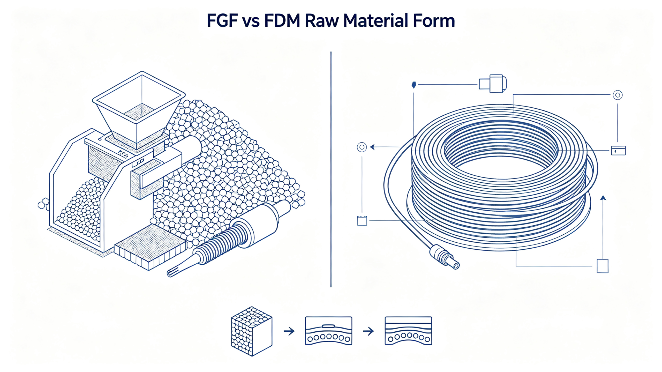
FGF, abreviatura de «Fused Granular Fabrication» (fabricación granular fusionada), también se conoce como impresión 3D por extrusión de gránulos o impresión 3D por extrusión con tornillo. Pertenece a la rama de la fabricación aditiva basada en la extrusión. La diferencia clave con respecto al proceso habitual FDM/FFF es que el FDM se alimenta de filamento en bobina, mientras que el FGF utiliza directamente gránulos de plástico y lleva a cabo la fusión y la deposición del material mediante un mecanismo de extrusión por tornillo.
Este cambio en el método de alimentación elimina el paso intermedio de convertir los gránulos en filamento. No solo reduce considerablemente los costes de materia prima, sino que también supera el límite de flujo de la extrusión de filamento, alcanzando una velocidad de deposición que se mide en kilogramos por hora. Esto hace que la tecnología FGF sea especialmente adecuada para el moldeado rápido de piezas de gran tamaño y gran volumen.
2. Principio de funcionamiento básico y arquitecturas de los equipos
2.1 Principio de plastificación en la extrusión por tornillo
El núcleo de un cabezal de impresión FGF es un sistema de extrusión con microhélice, cuya lógica de funcionamiento se asemeja mucho al cilindro de una máquina de moldeo por inyección. Una vez que los gránulos de plástico caen desde la tolva al cilindro, avanzan con la hélice giratoria y pasan sucesivamente por tres zonas funcionales:
- Zona de avituallamiento: Transporta gránulos sólidos y aplica un precalentamiento al material
- Zona de compresión: La profundidad del canal del tornillo disminuye gradualmente, lo que comprime y funde poco a poco los gránulos al tiempo que elimina el aire atrapado
- Zona de medición: El material se convierte en una masa fundida totalmente homogénea y se suministra de forma constante a la boquilla para garantizar un flujo de extrusión uniforme
A diferencia del FDM, que funde el filamento únicamente mediante conducción térmica, el tornillo FGF genera calor por cizallamiento en el interior de la masa fundida a medida que gira, calentando el material tanto por dentro como por fuera. Esta mayor eficiencia de plastificación es la razón principal por la que el FGF permite una extrusión de alto caudal.
2.2 Arquitecturas de equipos más habituales
Los equipos FGF de nivel industrial actuales utilizan principalmente dos arquitecturas, cada una de ellas adecuada para distintos escenarios de aplicación:
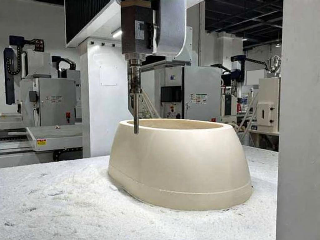
Sistemas de tipo pórtico Funcionan con coordenadas cartesianas, y el cabezal de impresión se desplaza a lo largo de los ejes X, Y y Z sobre un bastidor de pórtico rígido. Ofrecen una elevada rigidez estructural y una precisión de posicionamiento estable, y son idóneas para piezas de gran formato con geometrías regulares. Este diseño es, en la actualidad, la opción más habitual para la producción industrial.
Sistemas basados en brazos robóticos montar el cabezal de extrusión en un brazo robótico industrial de seis ejes, lo que permite un movimiento con múltiples grados de libertad. Permiten imprimir sin soportes superficies curvas complejas y estructuras con muescas, lo que las hace ideales para moldes de gran tamaño y formas especiales, esculturas y componentes arquitectónicos.
3. Diferencias clave entre el FGF y el FDM
Aunque ambas son tecnologías de impresión 3D basadas en la extrusión, la FGF y la FDM difieren considerablemente en cuanto a su aplicación y capacidades. La FGF es mucho más que una simple versión ampliada de la FDM.
| Dimensión de comparación | Impresión con gránulos de FGF | Impresión con filamento FDM/FFF |
|---|---|---|
| Forma de la materia prima | Gránulos de plástico | Filamento enrollado |
| Coste de las materias primas | Bajo, aproximadamente entre 1/3 y 1/5 del coste del filamento | Más alto, incluye la prima por procesamiento de filamentos |
| Tasa de deposición | Elevada; los modelos industriales alcanzan entre 5 y 20 kg/h | Bajo; normalmente cientos de gramos por hora |
| Espesor de la capa | Más grueso, normalmente de 0,5 a 2 mm | Más delgado, normalmente de 0,1 a 0,3 mm |
| Resolución de detalles | Moderado, diseñado para el conformado «near-net-shape» | Alta, capaz de reproducir detalles finos |
| Compatibilidad de materiales | Amplia gama; compatible con materiales altamente cargados, flexibles y reciclados | Limitado; los materiales deben cumplir los requisitos de estirado del filamento |
| Aplicaciones típicas | Herramientas de gran tamaño, moldes y piezas estructurales | Verificación de prototipos, piezas pequeñas, estructuras delicadas |
En pocas palabras, la tecnología FGF sacrifica algo de finura superficial a cambio de un rendimiento mucho mayor en cuanto a volumen de material y de ventajas más significativas en cuanto a costes. Su principal aplicación es el conformado de piezas de gran formato con forma casi definitiva, no la impresión de detalles de alta precisión.
4. Requisitos relativos al sistema de materiales y a los procesos de FGF
4.1 Incorporación de los materiales disponibles
El FGF es compatible con la gran mayoría de los gránulos termoplásticos aptos para inyección, lo que le confiere una selección de materiales mucho más amplia que la impresión con filamentos:
- Plásticos de ingeniería en general: PP, ABS, ASA, PETG, HIPS. Bajo coste, ideal para carcasas, moldes de embalaje y utillaje de uso general
- Plásticos técnicos de alto rendimiento: Nylon PA, PC, POM. Ofrecen una mayor resistencia mecánica y térmica para piezas estructurales funcionales
- Compuestos reforzados con fibra: Grados reforzados con fibra de vidrio y fibra de carbono. Mejoran considerablemente la rigidez y reducen la contracción, lo que los convierte en la mejor opción para moldes y utillajes de gran tamaño
- Elastómeros flexibles: TPU, TPE y otros materiales elásticos. La alimentación con gránulos es más estable que la alimentación con filamentos, con menor riesgo de deslizamiento u obstrucción
- Materiales reciclados y triturados: Los residuos triturados de extrusión y los gránulos reciclados pueden utilizarse directamente tras su secado y tamizado, lo que contribuye a los objetivos de fabricación sostenible.
4.2 Requisitos clave para el control de los procesos
La producción estable de FGF depende del control de dos condiciones fundamentales:
Control del contenido de humedad: Los materiales higroscópicos, como el nailon, el PETG y el PC, deben secarse completamente antes de la impresión. La humedad se evapora dentro del cilindro caliente, lo que genera burbujas que debilitan la adhesión entre capas e incluso pueden provocar defectos por huecos.
Adaptación del índice de fluidez: El índice de fluidez del material debe ajustarse a las especificaciones del tornillo y la boquilla. Una viscosidad demasiado alta provoca una presión de extrusión insuficiente y un flujo inestable; una viscosidad demasiado baja da lugar a descuelgues y a la acumulación de material, lo que perjudica la precisión del moldeado.
5. Directrices de diseño del FGF y límites de precisión
Para obtener los mejores resultados con un coste controlado, el diseño de las piezas debe seguir unos principios adaptados al proceso FGF.
5.1 Principios fundamentales de diseño
Adaptación del espesor de la pared: El FGF extruye un cordón relativamente ancho. Se recomienda un grosor de pared de al menos 2 mm, siendo preferible una pared uniforme de entre 3 y 8 mm para evitar detalles demasiado finos que no se puedan imprimir.
Gestión de las expectativas respecto a la textura de la superficie: Debido al mayor grosor de las capas, las piezas impresas presentarán una textura escalonada visible. En el caso de piezas con requisitos estéticos exigentes, hay que dejar un margen para el posprocesamiento y mejorar el acabado superficial mediante fresado, rectificado, pintura u otras operaciones secundarias.
Control de la contracción y la deformación: Las piezas de gran tamaño acumulan más tensión interna durante el enfriamiento, lo que aumenta el riesgo de deformación. Da prioridad a los materiales con fibra y optimiza la orientación de la impresión para reducir los tramos largos sin soporte.
Diseño de soportes: Los soportes para piezas pesadas deben tener suficiente capacidad de carga. Utiliza estructuras de soporte gruesas y fáciles de retirar, y colócalas estratégicamente para evitar que se derrumben durante la impresión.
5.2 Límites de precisión y posprocesamiento
La FGF es, por naturaleza, un proceso de “forma casi definitiva”. Las tolerancias dimensionales de las piezas recién impresas suelen situarse en un rango de ±0,5 a ±1 mm, lo que no es suficiente para un montaje de precisión. La solución estándar del sector es un flujo de trabajo híbrido de «impresión + mecanizado»: primero se imprime una pieza en bruto cercana a la forma final mediante FGF y, a continuación, se realiza un acabado CNC en las superficies de acoplamiento críticas y en los elementos de referencia. Este enfoque ofrece la precisión necesaria, al tiempo que reduce considerablemente la eliminación de material y mejora la eficiencia general.
6. Principales aplicaciones industriales de la tecnología FGF
Gracias a sus ventajas en cuanto a gran formato, bajo coste y entrega rápida, la tecnología FGF se ha implantado en una amplia gama de sectores industriales:
- Plantillas, accesorios y calibres: Grandes accesorios de montaje, plantillas de taladrado, calibres de inspección y mucho más. El fresado CNC tradicional a partir de material macizo genera un gran desperdicio de material. El conformado «near-net-shape» de FGF puede reducir el margen de mecanizado en más de un 70% y acortar el plazo de entrega varias veces.
- Moldes de fundición y cajas de machos: Modelos y cajas de núcleo para la fundición en arena. Los modelos tradicionales de madera son propensos a deformarse con la humedad y se desgastan rápidamente. Los moldes de plástico impresos con FGF ofrecen estabilidad dimensional, una larga vida útil y facilitan las modificaciones de diseño.
- Moldes para materiales compuestos: Moldes de gran tamaño para palas de aerogeneradores, paneles de carrocería de automóviles y otros productos. Impresos con material reforzado con fibra de carbono y con acabado en la superficie de trabajo, los moldes FGF acortan considerablemente los ciclos de desarrollo y reducen los costes de producción.
- Prototipos de interiores y exteriores de vehículos: Los prototipos de salpicaderos grandes, paneles de puertas y parachoques pueden imprimirse como una sola pieza sin necesidad de uniones, lo que permite un montaje rápido y la verificación del aspecto.
- Personalización arquitectónica y de mobiliario: Fachadas de edificios con formas especiales, mobiliario creativo, esculturas paisajísticas y otros productos de gran tamaño hechos a medida. FGF permite el moldeado integrado y ofrece una mayor libertad de diseño.
- Logística y revestimientos para embalajes: Cajas de gran capacidad, revestimientos acolchados, palés a medida y mucho más. Para la producción de bajos volúmenes, FGF resulta más rentable que fabricar un molde de inyección.
7. Selección de procesos para la fabricación de piezas de plástico de gran tamaño
Existen diversos procesos para la fabricación de piezas de plástico de gran tamaño. La elección adecuada depende del tamaño del lote, los requisitos de precisión, los objetivos de coste y el plazo de entrega:
| Solución de procesos | Ventajas | Limitaciones | Escenarios más adecuados |
|---|---|---|---|
| Impresión 3D de pellets de FGF | Sin costes de molde, entrega rápida, amplia selección de materiales | Precisión superficial moderada; mayor coste unitario en volúmenes muy elevados | Piezas de gran tamaño con forma casi definitiva, en lotes pequeños o medianos |
| Mecanizado CNC | Alta precisión y rendimiento estable del material | Gran desperdicio de material; difícil de aplicar en geometrías complejas; alto coste | Piezas estructurales de alta precisión y bajo volumen |
| Moldeo por inyección | Bajo coste unitario con grandes volúmenes, excelente uniformidad | Elevada inversión en moldes, ciclo de desarrollo prolongado | Producción en serie tras la finalización del diseño |
| Híbrido FGF + CNC | Combina velocidad y precisión, con un alto aprovechamiento del material | Requiere la coordinación de dos procesos distintos | Piezas funcionales de tamaño mediano a grande con requisitos de precisión muy estrictos |
En proyectos reales, los flujos de trabajo híbridos suelen ofrecer los mejores resultados. La tecnología FGF se encarga del modelado rápido y en bloque de la geometría principal, mientras que el mecanizado CNC garantiza la precisión en los elementos críticos. Esta combinación aúna la flexibilidad y la rapidez de la fabricación aditiva, al tiempo que conserva la precisión de la fabricación sustractiva.
Conclusión
La fabricación granular por fusión cubre el vacío existente entre la impresión 3D tradicional, de baja eficiencia, y el moldeo por inyección, de alto umbral de acceso. Ofrece una vía de fabricación rentable para la producción en lotes pequeños y medianos de piezas de plástico de tamaño mediano y grande. No pretende sustituir al FDM ni al moldeo por inyección, sino que abre una nueva vía de fabricación para aquellos casos en los que el gran formato, la rapidez de entrega y el bajo coste son factores determinantes.
A medida que se amplían las opciones de materiales y mejora la precisión de los equipos, la tecnología FGF está pasando de la producción de prototipos a la fabricación directa de piezas funcionales. Su ámbito de aplicación en los sectores de la fabricación de herramientas, la automoción, la industria aeroespacial, la construcción y otros seguirá creciendo.
PartsMastery ofrece servicios profesionales de impresión 3D con pellets FGF que abarcan PP, ABS, nailon, materiales con fibra de carbono y muchos otros materiales. Cubrimos todas las fases del ciclo de producción, desde la verificación de prototipos hasta la producción de lotes pequeños y medianos, y ofrecemos servicios complementarios de acabado CNC y tratamiento de superficies para proporcionar soluciones integrales de fabricación de piezas de gran tamaño a clientes de todos los sectores. Para evaluar su proyecto, suba su archivo CAD y recibirá un análisis completo del proceso y un presupuesto.