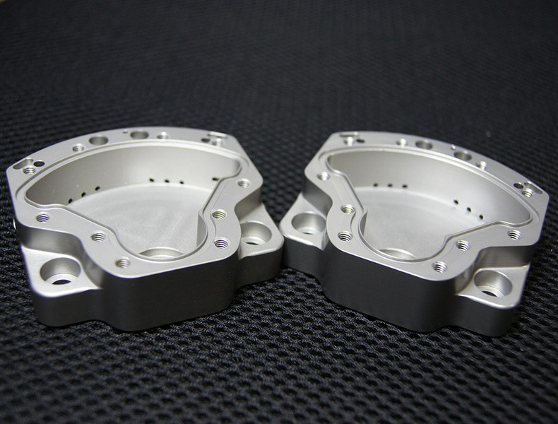
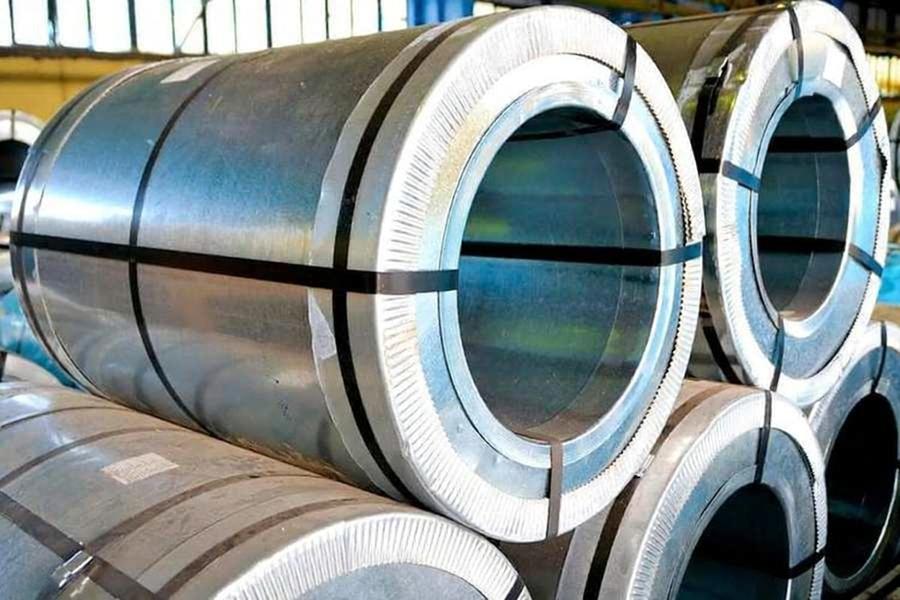
In CNC machining, material hardness is far more than a simple “soft” or “hard” label — it directly determines the cutting mechanism, tool life, parameter window, and final part accuracy. Although aluminum, copper, and brass can all be shaped by turning, milling, and drilling just like hardened steel and nickel-based alloys, the two categories differ fundamentally in cutting forces, cutting temperatures, chip morphology, and tool wear patterns. Understanding these differences is the prerequisite for developing sound machining plans, controlling tooling costs, and ensuring batch-to-batch consistency.
This guide starts from material classification benchmarks and systematically examines key stages including cutting mechanics, tool selection, parameter setting, chip evacuation, cooling, and quality control. It also provides quantified comparison data that engineers can directly apply in process reviews.
1. Material Classification and Hardness Benchmarks
Definition and Typical Alloys of Soft Metals
Soft metals generally refer to non-ferrous metals and alloys with a Brinell hardness below approximately 250 HBW and a tensile strength below 600 MPa. These materials share common characteristics: high ductility, low yield strength, and high thermal conductivity. Typical representatives include:
Aluminum alloys: 6061-T6 (~95 HBW), 7075-T6 (~150 HBW), with thermal conductivity of 150–200 W/(m·K). They represent the mainstream materials for aerospace and consumer electronics structural parts.
Copper and copper alloys: Pure copper (~40 HBW), brass C36000 (~80 HBW), bronze. They deliver excellent thermal and electrical conductivity but tend to be sticky and form built-up edge (BUE).
Magnesium alloys: AZ31B (~50 HBW), with a density of only 1.74 g/cm³. Cutting speeds can reach extremely high levels, but flammable chips demand special safety precautions.
Definition and Typical Alloys of Hard Metals
Hard metals generally refer to ferrous alloys and high-temperature alloys with a Brinell hardness above 300 HBW (or above HRC 30). These materials feature high yield strength, strong work-hardening tendency, and low thermal conductivity. During cutting, the tool withstands extreme mechanical and thermal loads. Typical representatives include:
Hardened steels: H13 tool steel (48–52 HRC), S7 tool steel, carburized and quenched AISI 4140 (50–55 HRC). Manufacturers commonly use these for dies, molds, and wear-resistant components.
Stainless and precipitation-hardening steels: 17-4PH H900 (~40 HRC), 316L stainless (work-hardens to ~250 HBW). These materials tend to be sticky and suffer from severe work hardening.
Nickel-based superalloys: Inconel 718 (~35 HRC, work-hardens to ~45 HRC), Hastelloy. Thermal conductivity measures only 10–25 W/(m·K), so cutting heat concentrates at the cutting edge.
Titanium alloys: Ti-6Al-4V (~30 HRC). Low elastic modulus causes springback, and high chemical reactivity triggers diffusion wear with tool materials.
2. Fundamental Differences in Cutting Mechanics
The cutting differences between soft and hard metals originate from the deformation behavior in the shear zone and the chip formation mode. Once engineers understand this layer, they can explain why tool angles, parameters, and cooling strategies diverge completely.
Shear Angle and Cutting Forces
Soft metals have low yield strength, so the shear angle typically measures large (40°–55°), the uncut chip thickness stays thin, and the main cutting force remains small. For 6061 aluminum, for example, the specific cutting force reaches approximately 70–100 N/mm² — only one-third to one-half that of medium carbon steel. Consequently, soft metal machining can employ large depths of cut and high feed rates, achieving extremely high material removal rates.
By contrast, hard metals present a small shear angle (15°–30°), a thick uncut chip layer, and significantly higher main and radial cutting forces. The specific cutting force of hardened steel can reach 250–400 N/mm², and Inconel 718 even exceeds 450 N/mm². High radial forces induce tool deflection, workpiece springback, and vibration. Therefore, hard metal machining remains extremely sensitive to machine rigidity and tool overhang control.
Chip Morphology and Chip Evacuation
Soft metals typically produce continuous, long spiral or ribbon chips. If operators fail to break these chips promptly, they can wrap around the tool and workpiece, scratch machined surfaces, and even create safety hazards. Therefore, the flute design of soft metal cutting tools focuses on “chip curling and breaking,” while high-pressure coolant flushes chips out of the cutting zone.
Hard metals, on the other hand, mostly yield short, fragmented C-type or arc-shaped chips. This occurs because high-hardness materials undergo severe plastic deformation and adiabatic shear in the shear zone, causing chips to fracture naturally. The chip evacuation challenge in hard metal machining is not chip wrapping — instead, it involves high-temperature chips burning the cutting edge and machined surface. Consequently, tool coatings and coolant must isolate and dissipate heat.
Cutting Temperature and Thermal Load
Soft metals have high thermal conductivity, so most cutting heat dissipates through the chips and workpiece, and the cutting edge temperature remains relatively low (typically below 300°C). However, at high cutting speeds, the chemical reactivity of aluminum and copper increases, making them prone to adhesion and diffusion with carbide tools, which forms a built-up edge (BUE).
Hard metals present the opposite situation. Low thermal conductivity means cutting heat cannot dissipate quickly through the workpiece, so a large amount of heat concentrates near the cutting edge (reaching 800–1200°C). High temperatures accelerate phase transformation softening and coating failure of the tool material. Therefore, hard metal machining must rely on tool materials with good hot hardness — such as ultra-fine grain carbide, CBN, and ceramics — and high-temperature-resistant coatings like TiAlN and AlTiN to withstand thermal loads.
3. Tool Selection Strategy Comparison
Tool selection represents the most visible manifestation of the differences between soft and hard metal machining. The two categories move toward opposite extremes in tool material, geometry, and coating strategy.
Soft Metals: Sharp, High-Rake, High-Gloss
When machining soft metals such as aluminum, copper, and magnesium, the core tooling objective is “sharp cutting and adhesion prevention.” Specific strategies include:
Tool material: Engineers should prioritize uncoated ultra-fine grain carbide (such as K10/K20 grades), or diamond coatings (PCD/CVD diamond) for high-gloss surfaces and ultra-long tool life. Coatings can actually increase aluminum adhesion tendency.
Geometry: Manufacturers use high rake angle (15°–25°), high relief angle (10°–15°), and high helix angle (35°–45°) to reduce cutting forces and material deformation. Cutting edges typically remain sharp (no hone) or receive micro-honing (below 0.02 mm).
Flute design: Large chip gullets and polished flute surfaces facilitate smooth evacuation of long chips and reduce friction between chips and the flute wall.
Hard Metals: Tough, Negative-Rake, Heat-Resistant
When machining hardened steels, nickel-based alloys, and titanium alloys, the core tooling objective shifts to “withstanding high loads and resisting wear.” Specific strategies include:
Tool material: Operators select tools based on hardness range. For 30–45 HRC, they use coated ultra-fine grain carbide. For 45–55 HRC, CBN (cubic boron nitride) or ceramic tools work well. For nickel-based alloys, they prioritize high-cobalt-toughness carbide or ceramics.
Geometry: Manufacturers employ low or negative rake angle (-5°–+5°), low relief angle (5°–8°), and low helix angle (25°–35°) to enhance cutting edge strength. They must hone edges (T-land, 0.05–0.2 mm × 20°–30°) or round them to prevent edge chipping.
Coatings: High-temperature-resistant coatings remain mandatory. TiAlN/AlTiN suits dry cutting and hard milling; TiCN suits medium-low hardness steels. Diamond coatings do not work for ferrous materials due to carbon diffusion.
Parameter
Soft Metal Machining
Hard Metal Machining
Tool material
Uncoated carbide, PCD diamond
Coated carbide, CBN, ceramic
Rake angle
15°–25° (high)
-5°–+5° (low/negative)
Relief angle
10°–15°
5°–8°
Helix angle
35°–45°
25°–35°
Edge preparation
Sharp or micro-hone
T-land hone or rounding
Coating
Usually uncoated or diamond
TiAlN/AlTiN/TiCN mandatory
4. Quantified Cutting Parameter Comparison
Cutting parameter settings directly affect machining efficiency, tool life, and surface quality. The following data represents industry-typical values. Engineers must adjust actual applications based on machine rigidity, tool overhang, and cooling conditions.
Parameter
Aluminum 6061
Brass C36000
Hardened Steel H13 (50 HRC)
Inconel 718
Cutting speed Vc (m/min)
300–800
200–400
80–200
30–80
Feed per tooth fz (mm/tooth)
0.1–0.3
0.08–0.2
0.03–0.1
0.02–0.08
Radial depth ae (mm)
0.5–1.0×D
0.3–0.8×D
0.1–0.3×D
0.05–0.2×D
Axial depth ap (mm)
1–2×D
0.5–1.5×D
0.1–0.5×D
0.1–0.3×D
Material removal rate Q (cm³/min)
50–200
30–100
5–20
2–10
The table clearly shows that the material removal rate of soft metals reaches 5–20 times that of hard metals. However, this does not mean soft metal machining can blindly pursue high parameters. Excessive cutting speeds cause built-up edge and burrs, while excessive feed rates induce vibration and surface roughness degradation. Hard metal machining, by contrast, has a narrow parameter window — any aggressive setting beyond the tool’s capacity leads to rapid wear or even catastrophic edge failure.
5. Cooling and Chip Evacuation Strategies
Soft Metals: High-Pressure, High-Flow Flushing
The cooling priority in soft metal machining is not temperature reduction — instead, it focuses on chip evacuation and preventing secondary cutting. Typically, operators use emulsified or semi-synthetic cutting fluids at 20–70 bar with sufficient flow rate, and they direct nozzles at the cutting zone. High-pressure coolant can break long chips and rapidly flush them out of the machining area, while also reducing workpiece temperature to minimize thermal deformation. For magnesium alloys, operators must use specialized cutting fluids and strictly control chip accumulation to prevent combustion risks.
Hard Metals: Precision Cooling or Minimum Quantity Lubrication
The cooling priority in hard metal machining shifts to reducing cutting edge temperature and minimizing thermal shock. For hardened steel milling, an increasing number of processes adopt dry cutting or minimum quantity lubrication (MQL), because TiAlN coatings form an aluminum oxide protective layer at high temperatures, which actually provides self-lubricating effects. If operators use coolant, they should employ through-coolant tools at 50–100 bar, ensuring coolant reaches the cutting edge directly. External cooling often fails to reach the cutting zone due to a vapor barrier effect. For titanium and nickel-based alloys, high-pressure through-coolant (70–150 bar) represents the standard configuration.
6. Surface Quality and Common Defects
Soft Metals: Burrs, Built-Up Edge, and Scratches
The surface quality challenges in soft metals come from three main sources. First, burrs — ductile materials tend to produce tear burrs at the edge exit side, especially at thin-wall edges and cross-holes. Second, built-up edge (BUE) — at medium-to-low cutting speeds, aluminum and copper can cold-weld onto the cutting edge. When BUE detaches, it carries away workpiece surface material, creating fish-scale defects. Third, chip scratches — if operators fail to evacuate long chips properly, they leave scratches on the machined surface.
Countermeasures include: using sharp tools to reduce exit tearing; increasing cutting speed beyond the BUE formation range (typically >300 m/min for aluminum); employing high-pressure coolant for forced chip evacuation; and reducing feed rate with a fresh sharp tool during finishing. For precision aluminum parts, a dedicated deburring operation should follow machining — manual, vibratory finishing, or thermal deburring all represent viable options.
Hard Metals: Vibration Marks, White Layer, and Burning
The surface quality challenges in hard metals differ entirely. First, vibration marks — high radial forces easily excite chatter in the machine-tool-workpiece system, leaving regular ripples on the surface that become both visible and tactile in severe cases. Second, white layer — after high-temperature cutting, the surface layer of hardened steel may undergo untempered martensitic phase transformation, forming a hard and brittle white layer that affects fatigue life. Third, surface burning — excessive cutting temperatures cause tempering discoloration (blue/yellow/brown) on the workpiece surface, reducing hardness.
Countermeasures include: minimizing tool overhang, increasing machine rigidity, and using variable-pitch tools to suppress chatter; controlling cutting temperature to avoid white layer formation, and using a combination of climb and conventional milling when necessary; and using small depths of cut, low feed rates, and sharp tools during finishing to ensure cutting heat does not exceed the tempering temperature. For critical components, surface hardness testing and metallographic inspection should follow machining to confirm the absence of white layer and burning.
7. Machining Efficiency and Tool Life Management
The efficiency bottleneck in soft metal machining is usually not the cutting itself — instead, it involves tool changes, chip evacuation, and part loading/unloading. Under optimized conditions, high-speed milling of aluminum can achieve material removal rates above 200 cm³/min, and tool life can reach several hours or even tens of hours. Therefore, soft metal machining should prioritize optimizing tool paths (such as trochoidal milling and high-speed dynamic milling) and automated loading/unloading to maximize machine utilization.
The efficiency bottleneck in hard metal machining, by contrast, centers on tool life. Tool life in hardened steel milling typically measures in minutes (10–60 minutes), and Inconel 718 may only last 5–20 minutes. Consequently, hard metal machining requires a strict tool life management system: operators force tool changes based on cutting time or number of parts machined, preventing worn tools from continuing in service and causing dimensional deviations and surface degradation. Additionally, manufacturers should employ online tool wear monitoring (such as spindle power monitoring and acoustic emission monitoring) to replace tools before they reach the wear criterion.
8. Process Planning and Quality Control
Machining Sequence Planning
Whether machining soft or hard metals, engineers should plan the division of roughing, semi-finishing, and finishing operations according to part geometry and functional requirements. However, the focus differs between the two categories. Soft metal machining emphasizes deformation control and burr prevention — therefore, stress relief or natural aging should follow roughing, and finishing uses small depths of cut to minimize elastic deformation caused by cutting forces. Hard metal machining emphasizes cutting stability and tool life — therefore, roughing uses large depths of cut with low feed rates to protect the tool, semi-finishing leaves a uniform finishing allowance (typically 0.1–0.3 mm), and finishing uses dedicated finish mills to guarantee dimensions and surface quality.
Workholding and Rigidity Control
Soft metal workpieces have low rigidity, so operators must avoid clamping deformation. They should use soft jaws, vacuum chucks, or dedicated fixtures, and distribute clamping forces evenly. Hard metal workpieces typically have good rigidity, but cutting forces run high — therefore, fixturing must remain robust and reliable. One-locator-two-pin setups or vise clamping work best to ensure no loosening during machining. For thin-wall hard metal parts, manufacturers can use filler materials (such as low-melting-point alloys) to increase rigidity, then remove them after machining.
In-Process Inspection and Dimensional Verification
After machining, inspectors should check dimensions and surface quality according to part requirements. For high-precision metal parts, micrometers, calipers, surface roughness testers, and coordinate measuring machines (CMM) can verify critical dimensions, tolerances, and surface parameters. Inspectors should carefully check soft metal parts for burrs, deformation, and surface scratches; they should carefully check hard metal parts for dimensional consistency, surface roughness, and the absence of white layer/burning. For batch production, manufacturers should establish SPC statistical process control to monitor Cp/Cpk of critical dimensions and ensure process capability meets requirements.
9. PartsMastery Precision Machining Capabilities
Equipment and Material Range
PartsMastery offers comprehensive CNC machining capabilities covering the full spectrum of soft and hard metals. Our facility houses 3-axis, 4-axis, and 5-axis machining centers, as well as CNC lathes and grinding machines. Machinable materials include aluminum alloys (6061, 7075, 2024), copper alloys (C36000, C11000), magnesium alloys (AZ31B), stainless steels (304, 316L, 17-4PH), tool steels (H13, S7, D2), hardened steels (up to 60 HRC), titanium alloys (Ti-6Al-4V), and nickel-based superalloys (Inconel 718, Hastelloy C-276).
Precision and Quality Assurance
Our secondary machining processes control precision within ±0.005 mm, and surface roughness can reach Ra 0.4 µm (finish milling) or Ra 0.1 µm (grinding). All parts undergo full CMM dimensional inspection before shipment, and we provide material certificates and inspection reports. From single prototypes to batch production, PartsMastery customizes optimal machining plans based on material characteristics.
10. Summary
The machining difference between soft and hard metals essentially boils down to a difference in cutting mechanics. Soft metals feature low cutting forces, high thermal conductivity, and long chips — the machining strategy revolves around “sharpness, high speed, and chip evacuation.” Hard metals feature high cutting forces, low thermal conductivity, and short chips — the strategy revolves around “toughness, temperature control, and wear resistance.” Neither category holds inherent superiority; they simply suit different application scenarios.
In practical projects, engineers should develop machining plans comprehensively based on material grade, hardness condition, part geometry, and functional requirements — not simply by setting cutting speed according to “soft” or “hard.” By properly matching tool material, geometry, cutting parameters, and cooling methods, manufacturers can ensure part quality consistency while maximizing machining efficiency and controlling overall manufacturing costs.
Frequently Asked Questions
Why are TiAlN-coated tools not recommended for machining aluminum?
TiAlN coatings have relatively high surface roughness and tend to bond with aluminum at aluminum cutting temperatures, which actually accelerates built-up edge formation. For aluminum machining, engineers should prioritize uncoated polished carbide or diamond-coated (PCD/CVD) tools. Sharp cutting edges and smooth flute surfaces deliver the best surface quality and tool life.
Should climb milling or conventional milling be used for hardened steel?
We recommend climb milling for hardened steel finishing. In climb milling, the cutting edge enters from thick to thin, cutting forces gradually decrease, and edge impact stays minimal, which helps protect the tool and achieve better surface quality. However, climb milling requires zero-backlash machine leadscrews and secure workholding. For roughing, operators can use conventional milling to protect the cutting edge from hard-scale impact.
Why is high-pressure through-coolant mandatory for titanium alloy machining?
Titanium alloys have extremely low thermal conductivity (~7 W/(m·K), only 1/6 that of steel), so cutting heat cannot dissipate through the workpiece. Over 80% of the heat concentrates near the cutting edge. External cooling often fails to reach the cutting zone due to the vapor barrier effect. Only high-pressure through-coolant (70–150 bar) — delivering coolant directly to the cutting edge through internal tool channels — can effectively reduce temperature and extend tool life. Additionally, high-pressure cooling helps evacuate chips and prevents secondary cutting.
How can you tell if a tool is worn out during hard metal machining?
Typical signals of tool wear in hard metal machining include: cutting sound becoming sharp or chattering; visible tool marks or burn discoloration on the workpiece surface; chip color changing from silver-white to blue/brown; spindle power or torque rising noticeably; and dimensions starting to go out of tolerance. We recommend establishing a tool life management table, setting tool change intervals based on actual machining tests (such as cutting time or number of parts), and mandating fresh tools before finishing to prevent worn tools from affecting final quality.