






Polymethyl methacrylate (PMMA), commonly known as acrylic, features high light transmittance, low density and excellent weather resistance. It also has good machinability for various forming processes.
It is widely used in display props, medical devices, lighting components, advertising signs, optical elements and automation equipment housings. CNC machining supports complex operations such as drilling, milling, engraving, slotting and trimming.
However, cracking remains one of the most frequent quality defects in acrylic production.
Crack defects have strong insidious characteristics. Some appear directly during the cutting process. Many more develop gradually during polishing, bonding, assembly or even after a period of product service.
These defects not only damage appearance integrity, but also reduce part structural strength. They often lead to batch rework and unnecessary cost losses.
Single parameter adjustment cannot fundamentally reduce acrylic cracking risk. Instead, systematic inspection is required across four core dimensions: material status, machining process, tooling & equipment, and post-processing & assembly.
Targeted optimization after root cause identification can steadily improve overall machining yield.
1. Pre-Machining Material Inspection: Eliminate Crack Risks at the Source
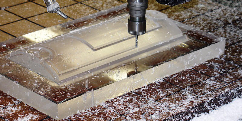
Not all acrylic cracking is caused by machining operations. Material quality, internal stress state and storage conditions are often hidden triggers.
If inherent defects exist in the material, cracks can easily appear in subsequent processes even with perfectly reasonable machining parameters.
1.1 Sheet Grade and Material Adaptability Verification
Acrylic sheets made by different production processes have significantly different machining performance. Material selection must match the precision requirements of the final part.
- Confirm raw material grade: Virgin material sheets have fewer internal impurities and uniform molecular structure. Recycled material sheets often have broken molecular chains and mixed impurities, which greatly increase edge chipping risk during machining.
- Check for apparent defects: Inspect sheets for internal bubbles, delamination and hidden cracks before machining. Uneven sheet thickness causes inconsistent cutting depth and aggravates local stress concentration.
- Distinguish forming processes: Cast acrylic sheets have low residual internal stress and good dimensional stability, making them ideal for high-precision parts. Extruded acrylic sheets offer higher production efficiency and lower cost, but carry higher residual stress and greater cracking risk in drilling and deep milling.
If microcracks already exist inside the sheet, mechanical stress during cutting will act as a trigger for crack expansion. Eventually, visible cracking defects will form on the finished part.
1.2 Internal Stress State and Annealing Pretreatment
Residual internal stress accumulates inside acrylic sheets during polymerization, transportation and stacking. This stress is invisible to the naked eye under normal conditions.
During high-removal processes such as drilling, slotting and deep milling, the original stress balance is broken. Stress releases along the cutting area and causes radial cracks around holes or microcracks on groove walls.
For sheets thicker than 10 mm, optical-grade transparent parts and high-precision components, annealing stress relief is strongly recommended before machining.
Step-by-step heating, heat preservation and slow cooling can effectively eliminate residual internal stress inside the sheet. This greatly improves machining stability and reduces the probability of delayed cracking.
1.3 Storage Environment and Material Status Confirmation
Acrylic has excellent weather resistance, but improper storage conditions will gradually degrade material performance. This becomes a hidden cause of later cracking.
- Long-term exposure to high temperature or direct sunlight accelerates material aging and reduces molecular chain toughness, leading to brittle fracture during machining.
- Moisture absorption in high-humidity environments affects dimensional stability and causes uneven stress release during cutting.
- Improper stacking and excessive local pressure cause permanent warpage and internal stress accumulation, leading to uncontrollable deformation during clamping and cutting.
Before machining, confirm that the sheet has no obvious warpage, yellowing or aging signs. This avoids processing scrap caused by poor initial material condition.
2. Machining Process Optimization: Control Cutting Heat and Stress Concentration
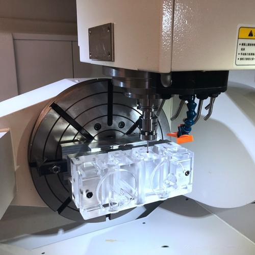
After excluding material factors, excessive cutting heat, cutting force impact and stress concentration are the core causes of acrylic cracking.
Systematic optimization of parameters, tool paths and processing procedures can effectively reduce cracking risk during the machining cycle.
2.1 Matching Adjustment of Cutting Parameters
Acrylic is a heat-sensitive material. It is far more sensitive to cutting temperature than common metals. Unreasonable parameter settings directly lead to heat accumulation and thermal stress cracking.
- Excessively high spindle speed and low feed rate prolong friction between the tool and the material. Local temperature rises rapidly, and the surface layer softens then cools down, forming new internal stress and eventually causing cracks.
- Excessive single cutting depth sharply increases cutting impact force, leading to forced cracking of the material. This effect is especially obvious in thin-walled and edge areas.
In actual production, match spindle speed, feed per tooth, cutting depth and machining allowance according to sheet thickness, tool diameter and operation type.
Maintaining a stable shear cutting state helps reduce frictional heat and stress concentration.
2.2 Layered Tool Path Planning
Acrylic parts with complex structures cannot be formed in a single cutting pass. Poor tool path design leads to local heat accumulation and stress concentration, which in turn causes cracking.
A layered machining strategy of roughing, semi-finishing and finishing is recommended for most complex parts.
- Remove allowance layer by layer to avoid large cutting force and high heat from single deep milling, and release machining stress gradually at the same time.
- Set arc transition and speed reduction at corners to avoid excessive tool dwell time and local overheating.
- Avoid repeated cutting in the same area to reduce heat accumulation and brittleness caused by work hardening.
For deep cavity, thin-walled and transparent display parts, this layered process balances dimensional accuracy, surface quality and crack resistance at the same time.
2.3 Rational Arrangement of Machining Procedures
Machining sequence directly affects the overall rigidity and stress distribution of the part. Improper procedure arrangement greatly increases cracking risk.
- Cutting the outer contour too early reduces the overall rigidity of the part. Subsequent inner cavity machining easily causes vibration deformation and edge cracks.
- Finishing thin-walled areas too early leads to deformation and microcracks under the cutting force of later processes.
- Arranging finishing procedures too early will be affected by stress release in subsequent roughing, resulting in dimensional deviation and surface cracking.
The reasonable procedure logic follows two basic principles. First, machine inner cavities and feature structures first, then cut the outer contour. Second, complete all roughing first, then gradually advance to semi-finishing and finishing.
This approach maintains sufficient overall rigidity throughout the process and disperses stress to the maximum extent.
3. Tool and Equipment Verification: Ensure Cutting Process Stability
Tools and equipment are the execution end of the cutting process. Improper selection, excessive wear or declining equipment accuracy will break stable cutting conditions.
These issues can easily induce edge chipping and microcracks on acrylic parts.
3.1 Selection of Special Cutting Tools for Acrylic
The cutting logic for acrylic is completely different from that for metal materials.
Special plastic cutting tools use optimized cutting geometry to achieve clean shear cutting. This effectively reduces extrusion deformation and heat generation.
- Large rake angle and sharp cutting edge design ensures clean material cutting, avoiding edge chipping and increased internal stress caused by extrusion.
- Polished chip flutes reduce chip evacuation resistance, cut down secondary heat from chip friction and improve final surface finish.
- Single-edge or double-edge structures adapt to acrylic cutting characteristics for smoother chip evacuation and less tool sticking.
Standard metal machining tools have cutting angles not optimized for plastics. They easily cause extrusion cracking and edge whitening, especially when processing transparent acrylic parts.
3.2 Proactive Management of Tool Wear Condition
New tools deliver the best cutting performance, but the cutting edge gradually dulls as production volume increases.
This wear is often invisible to the naked eye, but it first shows in machining quality: edge whitening, increased burrs, abnormal cutting noise, and eventually visible cracks.
A dull tool increases cutting resistance and frictional heat. Since acrylic is highly sensitive to heat and stress, these defects are quickly amplified.
In batch production, establish a formal tool life management mechanism. Replace or sharpen tools regularly according to machining volume, rather than waiting for obvious quality problems to appear.
This proactive approach maintains a stable cutting state from the source.
3.3 Machine Accuracy and Clamping Stability Inspection
Insufficient equipment accuracy and clamping failure cause vibration and uneven cutting force during machining, which induce edge chipping and cracks.
- Excessive spindle runout, excessive guide rail clearance and large transmission backlash cause micro-vibration of the tool. The cutting edge repeatedly impacts the material edge, forming microcracks that gradually expand.
- Insufficient fixture rigidity and loose workpiece clamping cause workpiece displacement or chatter during machining, destroying overall cutting stability.
Regular equipment accuracy calibration and maintenance, combined with optimized fixture design and clamping schemes, can significantly improve machining stability and reduce vibration-induced cracking.
4. Post-Processing and Assembly Control: Avoid Secondary Crack Risks
Many acrylic parts look perfect right after machining, but develop cracks during polishing, bonding or assembly.
Such secondary cracks are easily overlooked. Essentially, post-processing operations introduce new stress and trigger the expansion of tiny hidden defects.
4.1 Temperature Control in the Polishing Process
Polishing is the core process to improve acrylic edge finish, but both flame polishing and mechanical polishing generate heat. Improper temperature control will induce new internal stress.
- Too slow moving speed or repeated burning in the same area during flame polishing sharply increases surface temperature. Residual stress forms after cooling, leading to later cracking.
- Excessive pressure or too high polishing wheel speed in mechanical polishing also causes frictional heat and surface microcracks.
Select a suitable polishing process according to product requirements, and strictly control heating time and polishing pressure. Avoid local overheating that introduces secondary internal stress.
4.2 Standardized Operation of the Bonding Process
Acrylic bonding relies on special adhesives to dissolve the surface layer for material fusion. Improper operation directly causes stress cracking.
- Mismatched adhesive type or too fast curing speed leads to excessive shrinkage stress of the bonding layer, forming cracks along the bonding edge.
- Excessive adhesive dosage allows excess glue to seep into edge microcracks, accelerating crack propagation. This effect is especially obvious in transparent parts.
Select the corresponding adhesive model according to sheet thickness and structural strength requirements. Control adhesive dosage and curing speed to ensure bonding strength while avoiding stress concentration.
4.3 Stress Prevention in the Assembly Process
The assembly stage is a high-incidence scenario for delayed cracking. Cracks mostly concentrate in stress concentration areas such as mounting holes, corners and bonding seams.
- Over-tightened screws and too small fit clearance keep the part under long-term stress, gradually causing stress cracking.
- Insufficient thermal expansion allowance restricts material expansion and contraction with temperature changes. Internal stress accumulates continuously and eventually causes cracking.
- Forced assembly and impact installation create impact stress and hidden internal damage, which gradually expand during product service.
Reserve reasonable fit clearance and thermal expansion allowance during assembly, and control tightening force evenly. Avoiding forced assembly can effectively extend the service life of the final product.
5. Frequently Asked Questions
Q: Can acrylic parts with microcracks after machining continue to be used?
A: Judgment should be based on crack depth and specific location.
If the crack is only a very shallow surface machining mark, does not penetrate the material, and is not in a load-bearing area, it can be repaired by polishing or flame finishing before use.
If the crack has penetrated the material, is located in load-bearing areas such as mounting holes or load-bearing edges, or shows an obvious propagation trend, continued use is not recommended.
Long-term stress and temperature changes will cause the crack to extend continuously, reducing product safety and service life. When batch cracks occur, conduct a full-chain root cause investigation from material, process, tool to post-processing, and resume production after full optimization.
Conclusion
Cracking in acrylic CNC machining results from the coupling of multiple factors: material properties, machining process, equipment status and post-processing operations. Single parameter adjustment alone often fails to solve the problem fundamentally.
Systematic diagnosis should be carried out following the logic of material inspection, process optimization, equipment verification and post-processing control. Targeted improvements should be made after identifying the exact root cause.
For strict applications such as optical elements, medical device parts and high-precision transparent displays, stable machining quality directly determines product appearance, assembly performance and service life.
Establishing a standardized full-process management system covering incoming material inspection, process parameter standardization, tool life management and final product inspection can effectively reduce cracking risk and improve yield and stability in batch production.
PartsMastery specializes in precision plastic CNC machining services. With a mature acrylic machining process system, we provide stable and reliable custom machining solutions for various high-precision, high-appearance acrylic parts, helping customers improve product quality and production efficiency.