



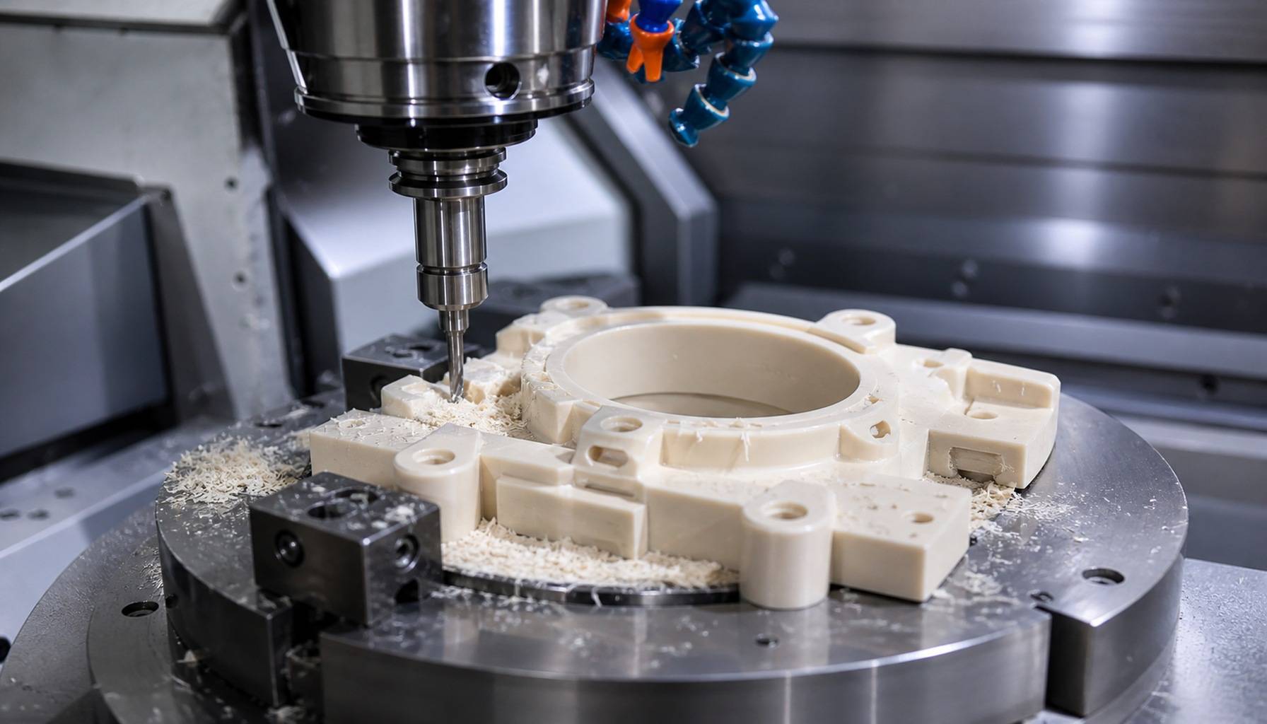
CNC plastic machining is a precision subtractive manufacturing process that produces custom plastic components from solid stock through computer-controlled cutting tools. Unlike injection molding, it requires no upfront tooling investment, making it ideal for functional prototypes, custom mechanical parts, and low-to-medium volume production runs.
With properly optimized process control, CNC machining can deliver tight tolerances, consistent dimensional accuracy, and smooth surface finishes across a wide range of engineering polymers. At PartsMastery, we specialize in precision CNC machining for high-performance plastic components, supporting customers from material selection and DFM review through final inspection and delivery.
1. Core Differences Between Plastic and Metal Machining
While both rely on CNC-controlled cutting tools, plastic and metal machining operate under fundamentally different constraints. Plastics have lower stiffness, poorer thermal conductivity, and higher sensitivity to heat and clamping force, which demands fully tailored tooling, parameters, and fixturing strategies.
Metal machining focuses heavily on tool wear management and cutting force control. By contrast, plastic machining prioritizes sharp cutting edges, effective chip evacuation, and heat buildup prevention to avoid melting, burr formation, and dimensional drift.
Most importantly, dimensional behavior differs significantly. Plastics expand and contract far more with temperature changes, and they can deform permanently under excessive clamping pressure. For this reason, parameters validated for aluminum or steel should never be directly applied to polymer materials.
2. Common Engineering Plastics for CNC Machining
To start with, selecting the right polymer is the first step in a successful plastic machining project. We select materials based on mechanical strength, thermal stability, chemical resistance, electrical insulation, and cost requirements.
2.1 General-Purpose Engineering Plastics
ABS offers good impact resistance, moderate stiffness, and excellent machinability, making it a popular choice for housings, brackets, and functional prototypes. HDPE delivers outstanding chemical resistance and toughness, well suited for wear strips, fluid handling components, and protective guards, though its high thermal expansion makes tight tolerance control more challenging.
2.2 Low-Friction Wear-Resistant Plastics
POM (acetal) stands as the widely preferred material for precision mechanical parts thanks to its low friction coefficient, good dimensional stability, and clean cutting behavior. It performs exceptionally well for gears, bushings, rollers, and guide components.
Nylon (PA6, PA66) combines high toughness and wear resistance for dynamic moving parts. It does, however, absorb moisture over time, which shifts its dimensions and mechanical properties, so it requires careful handling for high-precision applications.
2.3 Transparent Optical Plastics
Acrylic (PMMA) provides excellent optical clarity for display windows, protective covers, and optical panels. It is, however, brittle and prone to chipping or cracking if cutting forces or clamping pressure are not properly controlled.
Polycarbonate offers much higher impact resistance than acrylic, making it suitable for machine guards and protective enclosures. It scratches more easily and can develop stress cracking when exposed to incompatible chemicals, so processing and finishing must be carefully managed.
2.4 High-Performance Engineering Plastics
PEEK is a premium high-performance thermoplastic with outstanding mechanical strength, chemical resistance, and high-temperature capability. CNC-machined PEEK parts serve in medical devices, aerospace equipment, and industrial systems where reliability under extreme conditions is critical.
PTFE offers one of the lowest friction coefficients and broadest chemical resistance of any polymer, making it indispensable for seals, valve seats, and chemically exposed components. Its low stiffness and tendency to creep under load, however, increase machining and dimensional control difficulty.
| Material | Key Properties | Typical Components | Primary Machining Challenge |
|---|---|---|---|
| ABS | Good impact resistance, moderate stiffness | Housings, brackets, prototypes | Heat buildup, burr formation |
| POM (Acetal) | Low friction, good dimensional stability | Gears, bushings, precision parts | Thermal expansion control |
| Nylon (PA) | High toughness, good wear resistance | Rollers, guide components | Moisture absorption, dimensional shift |
| Acrylic (PMMA) | Excellent optical clarity | Windows, display covers | Chipping, edge cracking |
| Polycarbonate | High impact resistance, transparent | Machine guards, protective enclosures | Stress cracking, surface scratching |
| PEEK | High strength, heat and chemical resistance | Medical, aerospace, industrial components | Higher material cost, process control |
| PTFE | Ultra-low friction, broad chemical resistance | Seals, valve seats, liners | Creep, deformation under load |
3. Core Machining Processes & Quality Control
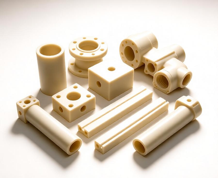
Put simply, plastic parts are primarily produced through three core CNC operations: milling, turning, and drilling. Each process requires specific tool geometry, cutting parameters, and fixturing to maintain consistent quality.
3.1 CNC Milling for Plastic Components
3-axis CNC milling handles most housings, brackets, plates, and contoured parts. For angled features, curved surfaces, and multi-sided parts, 4-axis or 5-axis machining reduces setups and improves positional consistency across features.
Sharp, high-rake-angle cutting tools reduce cutting forces and frictional heat. Proper chip evacuation is equally important, as trapped chips can reheat the workpiece and cause surface melting or dimensional distortion.
3.2 CNC Turning for Rotational Parts
CNC turning produces cylindrical features such as bushings, sleeves, spacers, and threaded components. POM is especially well suited for turning thanks to its stable cutting behavior and predictable dimensional behavior. PEEK, nylon, and PTFE can also be turned effectively, but each requires tailored feed rates and tool geometries.
3.3 Drilling and Hole Finishing
Drilling creates initial holes, which we can follow with reaming or boring for higher precision and better surface finish. For deep holes, chip evacuation is critical — accumulated chips generate excess heat and can damage hole walls or break tools.
3.4 Key Process Control Factors
- Tool selection: Sharp carbide tools with polished flutes reduce friction and produce cleaner cuts
- Cutting parameters: Balanced spindle speed and feed rate maintain consistent chip load and avoid overheating
- Cooling strategy: Compressed air is the standard method for chip removal and temperature control; liquid coolants require material compatibility verification
- Fixturing design: Distributed clamping pressure and supportive backing prevent clamping deformation, especially for thin-wall parts
4. Typical Applications and Industry Use Cases
Across industries, CNC machined plastic components serve a wide range of use cases where lightweight construction, electrical insulation, corrosion resistance, or low friction is required.
4.1 Automotive and Industrial Automation
In automotive manufacturing, machined plastics are used for prototype housings, electrical insulators, bushings, and assembly fixtures. In industrial automation, POM and nylon components are widely deployed in conveyor systems, robotic end effectors, and linear guides for their quiet operation and wear resistance.
4.2 Medical and Aerospace
Medical device manufacturers rely on CNC-machined PEEK and biocompatible polymers for instrument housings, lab fixtures, and fluid handling components. In aerospace, precision plastic parts serve as insulation pieces, lightweight brackets, and interior structural elements where weight savings and reliability are priorities.
4.3 Electronics and Consumer Products
Electronics applications include insulating plates, connector housings, sensor enclosures, and assembly jigs. For consumer product development, CNC plastic machining enables fast functional prototyping and design iteration before committing to high-volume tooling.
4.4 Chemical and Marine Equipment
PTFE, PEEK, and HDPE are common choices for valve seats, seals, liners, and corrosion-resistant components in chemical processing and marine equipment. These materials withstand harsh fluids and humid environments where metals would suffer accelerated degradation.
5. Precision Control and Common Defect Solutions
From a quality standpoint, final part accuracy depends on material stability, cutting temperature, fixturing, tool condition, and measurement conditions. Unlike metals, polymers are highly sensitive to thermal and mechanical influences, so precision control requires a holistic approach.
5.1 Realistic Tolerance Expectations
Rigid engineering plastics such as POM and PEEK can hold tighter tolerances than flexible or moisture-sensitive materials. As a general reference, ±0.05 mm is a practical baseline for most precision plastic features. Under strictly controlled conditions, selected features can reach ±0.02 mm, but such limits should always be validated for the specific material and geometry rather than assumed as a universal standard.
Thermal expansion has a measurable effect on final dimensions. For example, a polymer with a coefficient of linear thermal expansion of 100 × 10⁻⁶/K can shift a 100 mm dimension by roughly 0.10 mm with a 10°C temperature change. For this reason, precision measurements should always be performed under stable, documented environmental conditions.
5.2 Common Defects and Countermeasures
| Machining Issue | Typical Root Cause | Practical Solution |
|---|---|---|
| Melted or fuzzy edges | Excessive friction and heat buildup | Sharper tools, optimized chip load, improved air cooling |
| Warping and bowing | Residual stress release, uneven material removal | Balanced machining strategy, stress relief annealing, symmetrical tool paths |
| Chatter marks and vibration | Unsupported thin walls, excessive tool overhang | Additional backing support, shorter tool assemblies, reduced depth of cut |
| Excessive burrs | Dull tools, incorrect cutting geometry, too low feed rate | Sharp tool edges, optimized feed per tooth, dedicated deburring step |
| Stress cracking | Clamping deformation, chemical exposure, residual stress | Improved fixturing, compatible coolants, stress relief treatment |
6. Design Guidelines and Post-Processing Options
Good design for CNC plastic machining reduces deformation, improves tool access, and avoids unnecessary secondary operations.
6.1 Practical Design Recommendations
- Wall thickness: Maintain sufficient wall stiffness and avoid long, unsupported thin sections that can deflect under cutting forces
- Internal radii: Use generous internal corner radii compatible with standard tool diameters to reduce tooling cost and improve surface finish
- Deep cavities: Avoid excessively deep, narrow cavities that require long tools and increase vibration risk
- Threaded features: Consider thread length and repeated assembly cycles; metal thread inserts can improve durability for frequently fastened joints
- Critical tolerances: Apply tight tolerances only where functionally required to avoid unnecessary manufacturing cost
6.2 Available Post-Processing Finishes
After machining, plastic parts can receive various secondary treatments to improve appearance, performance, or functionality. We always verify compatibility for the specific polymer before production.
- Sanding and mechanical polishing: Remove tool marks and improve surface smoothness; can restore optical clarity for acrylic and polycarbonate when carefully controlled
- Bead blasting: Produces a uniform matte finish on compatible materials; we run pre-production tests on softer or brittle grades to avoid surface damage
- Stress relief annealing: Reduces internal residual stresses and improves long-term dimensional stability, especially useful for precision POM and PEEK components
- Laser marking: Adds permanent part identification, logos, or scale markings with minimal thermal impact when properly parameterized
- Coating and metallization: Apply decorative or functional surface layers; proper surface preparation is essential for good adhesion
7. Process Comparison: CNC Machining vs Injection Molding vs 3D Printing
Each manufacturing process has different strengths, and the best choice depends on volume, geometry, material requirements, and lead time.
| Manufacturing Process | Best Suited For | Key Advantage | Main Limitation |
|---|---|---|---|
| CNC Plastic Machining | Functional prototypes, custom parts, low-medium volume | No tooling cost, wide material choice, high precision | Higher per-unit cost at very high volumes, some geometric limitations |
| Injection Molding | High-volume repeat production | Low per-unit cost at scale, consistent aesthetics | High upfront tooling investment and long lead time |
| 3D Printing | Complex geometries, concept prototypes, very low volume | Greatest design freedom, fastest turnaround for simple parts | Limited material selection, lower dimensional accuracy, weaker layer properties |
In general, CNC machining is the strongest choice when you need solid engineering polymer materials, precise mechanical interfaces, and production quantities that do not justify injection mold tooling.
Conclusion
All things considered, CNC plastic machining is a versatile, reliable manufacturing method for producing custom precision components across a broad spectrum of engineering polymers. Success depends on matching the right material to the application, applying optimized tooling and process parameters, and controlling heat, fixturing, and measurement conditions throughout production.
At PartsMastery, we provide end-to-end CNC machining services for custom engineering plastic parts, including material consultation, DFM review, precision machining, surface finishing, and dimensional inspection. We support projects from early prototype development through low-volume and medium-volume production, helping customers bring high-quality plastic components to market efficiently and reliably.