






With the lightweight upgrade of aerospace, new energy vehicles and high-end sports gear, composite materials are gaining wider application.
Carbon fiber and glass fiber reinforced composites have become core materials for high-end equipment weight reduction.
They offer outstanding specific strength, specific modulus and corrosion resistance performance.
However, delamination, fiber pull-out and resin tearing remain persistent challenges in CNC milling.
Even with seemingly reasonable parameters, interlayer separation, edge fuzzing and exit splitting often appear.
These defects do not only damage part appearance.
They also directly weaken structural mechanical properties and shorten product service life.
Composite milling delamination never stems from a single factor.
It arises from the combined effect of material properties, tool condition, parameters and clamping setup.
Therefore, a full-process systematic optimization is required to solve the problem stably.
1. Root Causes of Delamination in Composite Milling
1.1 Intrinsic Structural Properties of Composite Materials
The anisotropic structure of composites is the fundamental internal cause of delamination.
Unlike homogeneous metals, composites consist of reinforcing fibers and a resin matrix.
Their interlaminar bond strength is far lower than the axial strength of fibers:
- Fibers carry the main load, but have weak transverse shear resistance. Lateral cutting force easily causes fiber fracture and pull-out.
- Resin matrix acts as the bonding phase, with limited heat resistance and toughness. Local cutting heat can easily cause resin softening and cracking.
- Interlaminar interfaces are mechanical weak zones. Separation force perpendicular to plies easily breaks the interface and causes peeling.
When cutting load exceeds interface bond strength, material removal shifts from shearing to tearing.
As a result, delamination defects start to form and expand.
This also explains why the process window for composites is much narrower than for metals.
1.2 Dynamic Effects of Milling Mechanics
The intermittent nature of CNC milling causes periodic changes in cutting force direction.
Composites are highly sensitive to load direction, which is a key dynamic trigger of delamination:
- In conventional up milling, the cutting edge engages material from bottom to top. It tends to peel surface fibers and cause fuzzing and tearing.
- Excessive feed rate leads to sharp impact load per tooth. It accelerates crack propagation and causes interlaminar cracking.
- A worn cutting edge loses shearing ability and turns to extrusion and friction. It increases cutting force and raises friction heat, further weakening resin strength.
1.3 Coupling Effect of Process and Tooling
Unreasonable process design and clamping setup will amplify delamination risk.
They act as the direct external cause of machining defects:
- Mismatched spindle speed and feed rate cause excessive per-tooth load and stress concentration.
- Sharp turns or vertical plunging in toolpath cause sudden load changes and trigger interlaminar cracks.
- Insufficient clamping stiffness and large overhang span intensify machining vibration. The fluctuating load repeatedly impacts the interlaminar interface.
2. Tool System Optimization: Core Defense Against Delamination
Tooling directly determines the material removal mechanism.
Selecting suitable tools and maintaining sharp edges is the first line of defense against delamination.
2.1 Use Specialized Tools for Composite Machining
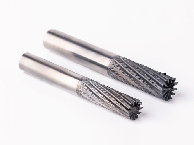
Specialized fiber-cutting tools should be prioritized over general metalworking tools.
They reduce tearing risk from the very principle of cutting:
- PCD diamond coated tools: Far more wear-resistant than standard coatings. They maintain edge sharpness for a long time and avoid extrusion-induced delamination.
- Ultra-fine grain carbide tools: Offer better toughness and edge stability. They reduce micro-chipping and prevent fiber pulling defects.
- Shear-type helical end mills: Optimized cutting angles achieve clean shear cutting. They greatly reduce fiber pull-out and interlaminar peeling.
2.2 Optimize Tool Geometric Parameters
Tool geometry directly changes cutting force distribution and material failure behavior.
Targeted parameter optimization can effectively lower delamination tendency:
- Moderately increase rake angle: Reduce extrusion effect of the cutting edge, strengthen shear action and lower lateral force.
- Use smaller helix angle: Reduce axial pulling force during cutting and lower separation load perpendicular to plies.
- Maintain high edge sharpness: Ensure fibers are cut cleanly instead of being pulled out, and reduce fuzzing at surfaces and exits.
- Optimize chip evacuation structure: Avoid secondary scraping of machined surfaces and prevent extra interlaminar damage.
2.3 Strictly Control Tool Wear Condition
Tool wear is the most overlooked cause of delamination, and its damage is cumulative:
- Edge wear gradually turns cutting into extrusion and friction. Delamination risk rises exponentially with wear level.
- Coating peeling increases friction heat and accelerates resin matrix softening, further reducing interlaminar strength.
- A tool life management standard must be established. Combine in-process wear monitoring for timely tool change to avoid batch delamination.
3. Process Parameter and Toolpath Optimization: Precise Load Control
Controlling the magnitude and direction of cutting load is the core principle of composite milling.
Only stable and controllable load can prevent interface failure.
3.1 Follow High-Speed, Low-Feed, Small-Depth Principle
A proper parameter combination can effectively reduce cutting impact and stabilize material failure:
- Moderately raise spindle speed: Lower per-tooth cutting load, keep fibers under continuous shear and reduce impact damage.
- Control feed rate: Reduce instantaneous impact load and prevent sudden interface failure from stress spikes.
- Adopt layered milling with small depth of cut: Disperse cutting stress, keep single-pass force below interface strength threshold, and remove stock step by step.
3.2 Design Low-Stress Toolpaths
Toolpath directly determines stress distribution and failure propagation direction.
Optimized paths can reduce delamination risk at the load transfer level:
- Prefer cutting along fiber ply direction: Reduce lateral pulling force on fibers and improve machined surface integrity.
- Avoid sharp path turns: Sharp turns cause sudden load changes, local stress concentration and interlaminar cracks.
- Use helical ramp plunging: Replace vertical plunging impact for smooth engagement and reduced initial delamination.
- Apply climb milling mode: The edge cuts from top to bottom, presses surface material down and avoids peeling from up milling.
3.3 Special Treatment for High-Risk Areas
Part edges, exit sides and hole peripheries have the highest delamination risk.
They require differentiated process strategies:
- Reduce feed rate at edges and exit areas to lower impact load during tool breakthrough.
- Add backing plates or sacrificial layers on the exit side to absorb breakthrough impact and suppress exit splitting.
- Adopt step-by-step hole machining — pre-drilling, reaming and finishing — to avoid hole perimeter delamination from single-shot drilling.
- Arrange local finishing passes on high-stress areas to improve edge integrity with light stock removal.
4. Clamping and Support System: The Overlooked Key Factor
Composites have lower stiffness than metal materials.
Clamping stiffness and support layout directly affect machining stability.
This is a frequently ignored but highly influential factor for delamination.
4.1 Improve Overall Clamping Stiffness
Stable support is the foundation for reducing vibration and deformation:
- Use vacuum chuck clamping: Delivers evenly distributed support force, avoids stress deformation from local clamping and improves overall fitting stiffness.
- Add local support blocks under the machining area to reduce workpiece overhang and suppress vibration amplification.
- Avoid large unsupported spans to prevent workpiece chatter and aggravated interlaminar fatigue damage.
4.2 Control Clamping Deformation and Vibration
Improper clamping force will introduce internal stress.
Stress release after machining can easily cause delamination and deformation:
- Adopt symmetric clamping to ensure uniform force and avoid warping from unbalanced load.
- Control clamping force level. Ensure secure holding while avoiding resin matrix damage and internal stress buildup from over-clamping.
- Optimize support point layout to align support positions with cutting load positions and improve structural stability.
4.3 Strengthen Exit-Side Support Design
The tool breakthrough stage has the highest delamination occurrence rate.
A dedicated end support line of defense must be built:
- Install a rigid backing plate on the exit side to absorb instantaneous breakthrough impact and stop interlaminar peeling.
- Use a sacrificial layer of similar material to avoid edge chipping and tearing during tool breakthrough.
- Combine with reduced feed rate at the exit section to further lower breakthrough load and improve edge quality.
5. Full-Process Upgrade: From Passive Repair to Active Prevention
The core of high-end composite machining is precise control of material failure behavior.
It should never rely on post-machining patching and rework.
5.1 Prioritize Source Prevention
Most composite delamination defects are irreversible.
Once interlayer separation occurs, polishing or patching can only improve appearance.
It cannot restore the original structural mechanical strength:
- Process optimization must take priority over any surface repair methods.
- Establish a prevention-first quality control logic and move delamination control to the process design stage.
5.2 Adopt a Multi-Stage Machining Strategy
Splitting the process into multiple stages can gradually release stress and reduce overall risk:
- Roughing stage: Remove most stock with higher parameters, focusing on material removal efficiency.
- Semi-finishing stage: Leave uniform finishing stock, release roughing internal stress and stabilize workpiece structure.
- Finishing stage: Apply optimized low-load parameters, focusing on surface quality and edge integrity.
5.3 Build an In-Process Monitoring Closed Loop
Real-time process monitoring further improves process stability and prevents batch quality accidents:
- Deploy cutting force monitoring systems to track load changes in real time and identify tool wear and abnormal load early.
- Adjust machining parameters dynamically based on tool condition feedback to keep the cutting process stable and controllable.
- Set up abnormal warning and shutdown mechanisms to prevent whole-batch delamination scrap from out-of-control machining.
Conclusion
Composite milling delamination results from the coupling of material properties, tool condition, process parameters and clamping setup.
Single parameter adjustment or tool replacement cannot solve the problem fundamentally.
Only a full-process optimization system covering tool selection, process design, clamping support and process control can stably control delamination.
In this way, manufacturers can achieve a balance between machining quality and production efficiency.
PartsMastery has deep expertise in high-end composite CNC machining.
We provide proven milling process optimization and tool matching solutions.
We deliver customized machining plans for different material systems and part structures.
Our solutions systematically solve delamination problems at the process source.
They help clients improve product yield and machining efficiency at the same time.
Author: PartsMastery Technical Team