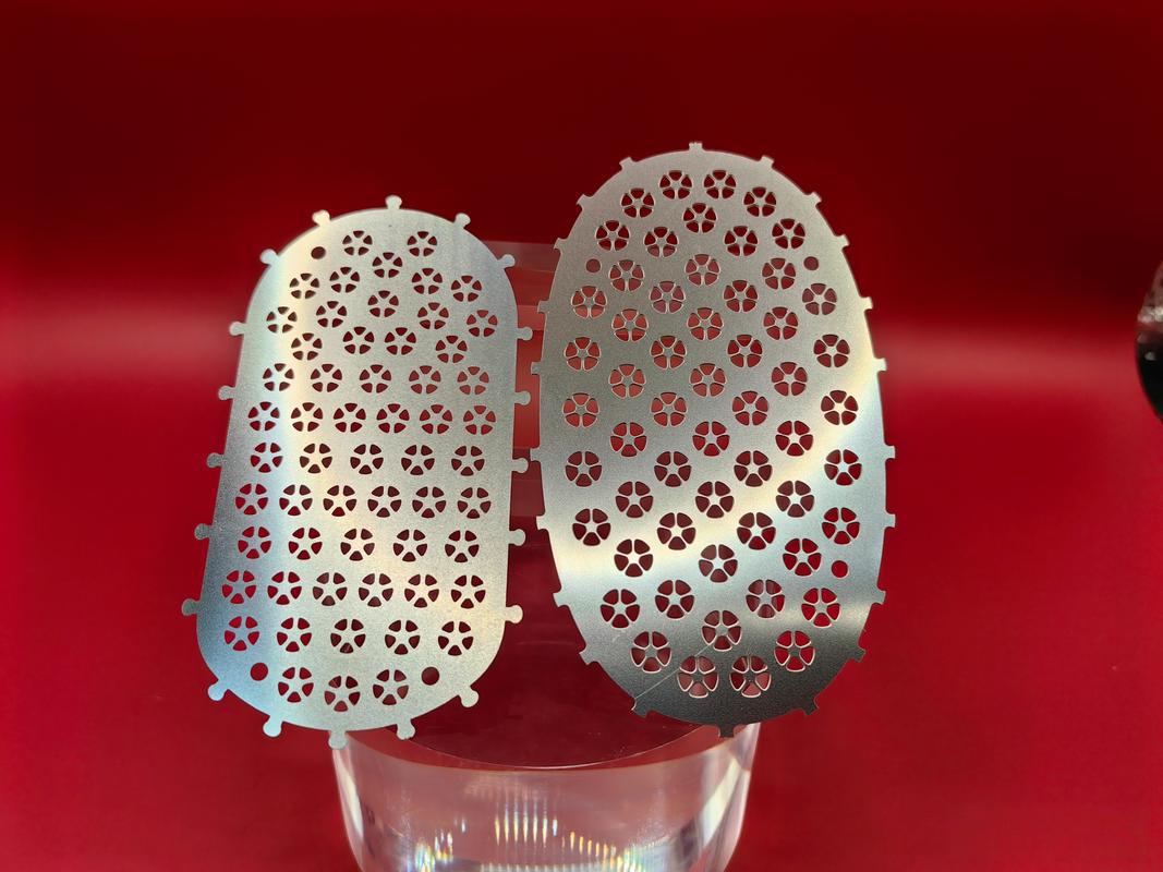
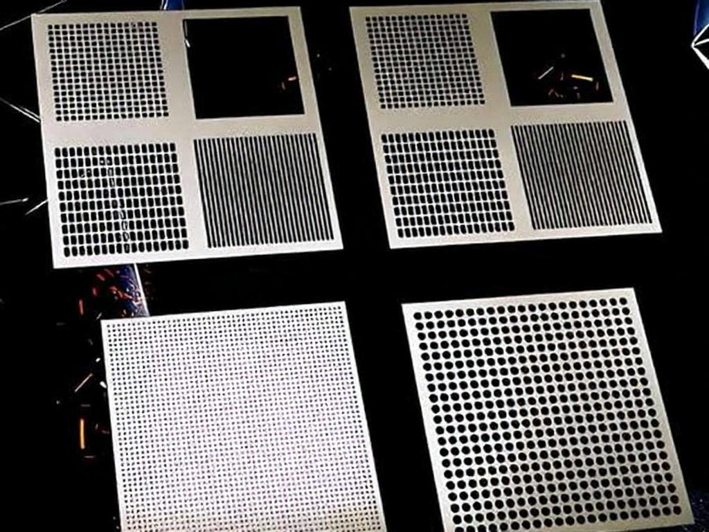
When precision thin metal parts require dense micro holes, narrow slots, fine ribs or complex planar profiles, and traditional cutting methods tend to produce burrs or stress deformation, chemical etching often emerges as a more optimal solution. Beyond through cutting, it can also create half-depth features such as grooves, fold lines and identification marks on metal surfaces, removing material entirely through chemical reactions without cutting tools or concentrated heat input.
These unique properties deliver distinct advantages, but the process is not the best choice for all metal parts. Material type, sheet thickness, feature geometry, etch depth, tolerance requirements and production scale all influence its suitability. Understanding the relationships across these dimensions is the first step in choosing between etching, engraving, stamping, laser cutting and machining.
1. What Is Chemical Etching?
Chemical etching is a selective subtractive manufacturing process that dissolves unprotected areas of a metal sheet using chemical reagents. A patterned photoresist layer protects the geometry that must be retained, while the etchant creates through cuts or recessed features at controlled depths.
Industrial precision metal chemical etching is also referred to as photochemical etching, photo etching or photochemical machining, while “chemical processing” is a broader term. Acid etching can describe both industrial material removal and decorative surface treatment. Production-grade precision etching relies on coordinated control of imaging, registration, chemical reaction, inspection and material management.
2. Complete Chemical Etching Process Flow
Chemical etching converts digital patterns into protected and exposed areas on a metal sheet to produce the final part. The full production workflow typically consists of four core stages.
Step 1: Material Preparation & Surface Cleaning
Before production, the alloy grade, temper condition, sheet thickness, panel size, grain direction and incoming material state are verified. The sheet surface then goes through multiple cleaning stages to remove oil and oxide, ensuring uniform and strong adhesion of the photoresist. Material condition and surface cleanliness directly affect final etching accuracy and consistency.
Step 2: Photoresist Coating & Pattern Transfer
A UV-sensitive photoresist is uniformly applied to the metal sheet. Using precisely aligned photomasks or digital imaging technology, the CAD geometry is accurately transferred onto the resist layer. For critical features such as through holes, slots and outer contours, double-sided registration enables higher dimensional control.
Step 3: Development & Chemical Etching
The development step removes photoresist from non-protected areas, exposing the metal surface to be etched. The etching machine then sprays chemical reagents under controlled parameters; reagent concentration, temperature, spray pressure and reaction time collectively determine the material removal rate.
Because chemical attack occurs in both vertical and lateral directions, pattern designs must compensate for undercut in advance. PartsMastery can achieve controlled depth etching from 25% to 75% of sheet thickness for features such as grooves, bend lines, recessed marks and stepped profiles. Final results are subject to DFM (Design for Manufacturability) review based on feature width, depth, sidewall angle, material and tolerance requirements.
After residual photoresist is removed and multiple cleaning cycles are completed, parts are inspected for dimensions and appearance according to drawing requirements. Finished parts can be delivered with tabbing for handling convenience or as individual pieces, and can be followed by secondary operations such as forming, electroplating, passivation, heat treatment, bonding, welding or assembly.
3. Core Equipment & Etching Chemistry
A complete chemical etching production line typically includes cleaning and rinsing units, coating/lamination equipment, UV exposure or digital imaging systems, developers, spray etching machines, resist stripping equipment and optical inspection devices.
Ferric chloride is a widely used general-purpose etchant, but the exact chemical formulation must be matched to the alloy type and desired results. Aluminum, copper, nickel, carbon steel, stainless steel and titanium have very different chemical reaction characteristics. Therefore, chemical storage, workshop ventilation, operator protection, pure water rinsing and waste treatment are all essential supporting components of a production system.
4. Compatible Materials & Typical Applications
Chemical etching is mainly applied to flat metal sheets and foils. PartsMastery supports etching of aluminum, brass, copper, carbon steel, stainless steel, titanium alloys, silver, nickel and many other materials. Alloy composition, temper condition, oxidation level, sheet thickness and surface requirements all affect process feasibility and final results.
Common etched parts and features include:
Sealing gaskets, spacers, screens, filters and precision mesh components
Electrical contacts, flexible springs, profiled slots, micro holes and complex openings
Pre-bend score lines, functional grooves, depth marks and stepped surfaces
Complex flat profiles with dense, repeating fine features
The process is widely used in aerospace, automotive, electronics, automation, robotics and consumer electronics, and is especially well suited for ultra-thin precision stainless steel parts. Etched copper and brass components are commonly found in electrical connection and thermal conduction applications. The core criterion for process suitability is part geometry and functional requirements, not industry classification.
5. Key Advantages of Chemical Etching
For compatible thin metal parts, chemical etching offers several unique benefits that traditional processes cannot match:
No cutting stress or heat-affected zone: The process applies no mechanical force and generates no localized high heat, preserving the structural properties of delicate sheets and preventing part deformation.
Naturally burr-free edges: Material is removed uniformly by chemical reaction, leaving no hard burrs from stamping or milling, and eliminating secondary deburring operations.
Highly flexible digital tooling: Design changes only require digital file updates, no dedicated hard tooling, making it ideal for complex repeating features and fast design iterations.
Seamless scaling from prototype to production: The same process route covers single prototypes and low-to-medium volume production without switching manufacturing methods.
Multi-depth feature compatibility: Both through cuts and half-depth recessed features can be produced on the same part, expanding the functional design of flat components.
These advantages must still be weighed against undercut, sheet thickness, edge geometry, tolerance requirements and production volume — no single manufacturing process works for every application.
6. Tolerance Standards & Design Considerations
Material removal in chemical etching occurs in three dimensions. Lateral etching creates chamfered sidewalls and tapered edges. For this reason, the relationship between sheet thickness and minimum hole diameter, slot width and web width is a core DFM principle.
The values below serve as preliminary planning references for PartsMastery chemical etching projects. They are for evaluation only and do not represent guaranteed final specifications. Actual manufacturing capability is determined by alloy grade, thickness, part geometry, sheet size, order volume, process configuration and inspection requirements.
Sheet Thickness
Preliminary Dimensional Tolerance
0.001 in
±0.0008 in
0.002 in
±0.0016 in
0.005 in
±0.0025 in
0.010 in
±0.0033 in
0.015 in
±0.0042 in
0.020 in
±0.0050 in
0.040 in
Requires engineering review
Minimum manufacturable feature sizes also vary with sheet thickness. Preliminary design guidelines are as follows:
Feature Type
Preliminary Design Reference
Holes / slots in 0.001–0.005 in thick material
Minimum size ≥ material thickness; minimum slot width 0.003 in, minimum hole diameter 0.005 in
Holes / slots in 0.005 in and thicker material
Minimum size ≥ 1.1 × material thickness
Webs / cantilevers in material under 0.005 in thick
Minimum width ≥ material thickness; absolute minimum 0.003 in
Webs / cantilevers in material over 0.005 in thick
Minimum width ≥ 1.0 × material thickness
Because center-to-center and edge dimensions originate from the same image layer, they can be controlled more precisely than independent edge dimensions. Preliminary tolerance references for center-to-center dimensions:
Center-to-Center Dimension Range
Preliminary Tolerance Reference
1.01 in and under
±0.001 in
1.01–3.0 in
±0.003 in
3.0–6.0 in
±0.005 in
6.0–10.0 in
±0.007 in
A complete DFM review also covers internal corner transitions, tab layout, rolling grain direction, nesting efficiency, surface roughness requirements, etch depth uniformity, sheet flatness, packaging strategy and compatibility with subsequent forming operations. A qualified supplier evaluates feasibility across all conditions rather than judging manufacturability by a single metric.
7. Chemical Etching vs Engraving vs Chemical Milling
Etching and engraving are both material removal processes, but they serve different manufacturing purposes. Chemical milling operates on similar principles as chemical etching, yet each targets different application scopes.
Comparison Dimension
Chemical Etching
Engraving
Chemical Milling
Primary Purpose
Precision thin metal part forming and functional grooves
Surface text, graphics, codes and identification marks
Controlled material removal over large areas
Removal Mechanism
Chemical reaction under patterned photoresist
Mechanical cutting, laser ablation or other marking methods
The difference is not simply “chemical vs mechanical”. Laser engraving, chemical engraving and acid etching are all valid marking approaches. The more important distinction is the end goal: producing legible surface marks, functional recessed features, or complete thin metal part geometry.
Chemical milling generally refers to uniform material removal over relatively large areas, often used for structural weight reduction and section control in aerospace. Precision photochemical etching focuses more on fine features on thin sheets, though the two terms sometimes overlap. Design drawings should clearly specify final geometry and depth requirements instead of relying solely on process terminology.
8. When to Choose Chemical Etching
Chemical etching is the best fit for thin, flat parts with many repeating fine features, requirements for burr-free edges, and sensitivity to cutting stress or heat effects. It is also highly useful for projects with frequent design changes, since digital tooling can be modified without new hard tooling.
If a part is thick, dominated by three-dimensional geometry, requires deep grooves, needs perfectly square cut edges, or has features that conflict with thickness-to-feature ratio rules, another process may be more appropriate. CNC machining can produce complex 3D geometry; laser cutting works well for fast blanking of large sheet sizes; stamping delivers excellent cost efficiency for stable high-volume production once tooling costs are amortized. For surface marking only, engraving is usually the more straightforward choice.
Process selection should combine material, thickness, geometry, tolerance, edge condition, volume, inspection standards and downstream operations. A drawing-based DFM review provides more reliable guidance than comparing process advantages in isolation.
9. How to Start a PartsMastery Chemical Etching Project
If your drawings involve thin complex metal structures, through / half-through / stepped etch features, flexible digital tooling requirements, or need integration with forming, surface finishing, machining and assembly, PartsMastery provides complete chemical etching solutions.
To streamline the review process, please provide the following information when submitting your project:
CAD files and controlled revision drawings
Material grade, temper condition and sheet thickness
Prototype quantity and expected production volume
Requirements for through-hole etching and partial-depth features
Critical dimensions, datums and inspection acceptance criteria
Secondary operations such as forming, plating, passivation or assembly
Submit your project through PartsMastery’s chemical etching service channel to receive professional DFM feedback and a custom quote. Our engineering team confirms feature limits and tolerance ranges based on actual material and geometry, not just preliminary reference tables.
Final Takeaways
Chemical etching produces precision thin metal parts through patterned protection and chemical dissolution, and excels at dense micro holes, complex profiles, burr-free edges and controlled-depth features. Its main design limitations come from sidewall chamfering, material reaction characteristics, thickness-to-feature constraints and depth control accuracy.
PartsMastery provides end-to-end etching services from prototype to batch production, covering through etching, half etching and step etching, with supporting digital tooling, precision inspection and downstream secondary processing. Submit your complete drawings, material specs, thickness, critical dimensions and etch depth requirements for a customized DFM review and project quote.
FAQ
Can etched parts be formed or plated afterward?
Yes. Depending on material and design, etched blanks can undergo subsequent bending, electroplating, passivation, heat treatment, bonding, welding or assembly. Operation sequence matters, as forming and finishing may alter part dimensions, surface condition and inspection datums.
How are critical etched features inspected?
Drawings must clearly specify datum locations, critical hole/slot dimensions, center-to-center tolerances, etch depth and surface finish requirements. Inspection can use optical measuring instruments, automated vision systems, dedicated gauges or other suitable equipment. Sampling inspection, first-article inspection or 100% inspection should be agreed upon before production.
When is stamping better than chemical etching?
Stamping becomes more cost-effective when part geometry is stable, production volume is large enough to amortize hard tooling costs, and the process can reliably produce the required features. However, for designs with frequent changes, a need for flexible tooling, or parts with dense fine features, chemical etching remains the more efficient choice.
Can the same etching process support both prototyping and production?
Yes. The same chemical principles and process route can be used for both development prototypes and repeat batch production. Before scaling to volume manufacturing, drawing revisions, artwork files, material specifications, process parameters, inspection plans, packaging methods and all secondary operations should be finalized to ensure batch-to-batch consistency.