






CNC drilling is one of the most fundamental and core processes in precision manufacturing, widely used for machining brackets, housings, manifolds, fixtures, heat sinks and various other components. The positional accuracy, thread quality and burr control of holes directly determine the assembly reliability of parts and the overall performance of finished products.
This article systematically sorts out the process logic, common hole types, material compatibility, design optimization and quality inspection methods of CNC drilling, providing engineers and procurement personnel with a full-process reference from design selection to project implementation.
1. Definition and Process Characteristics of CNC Drilling
1.1 What is CNC Drilling
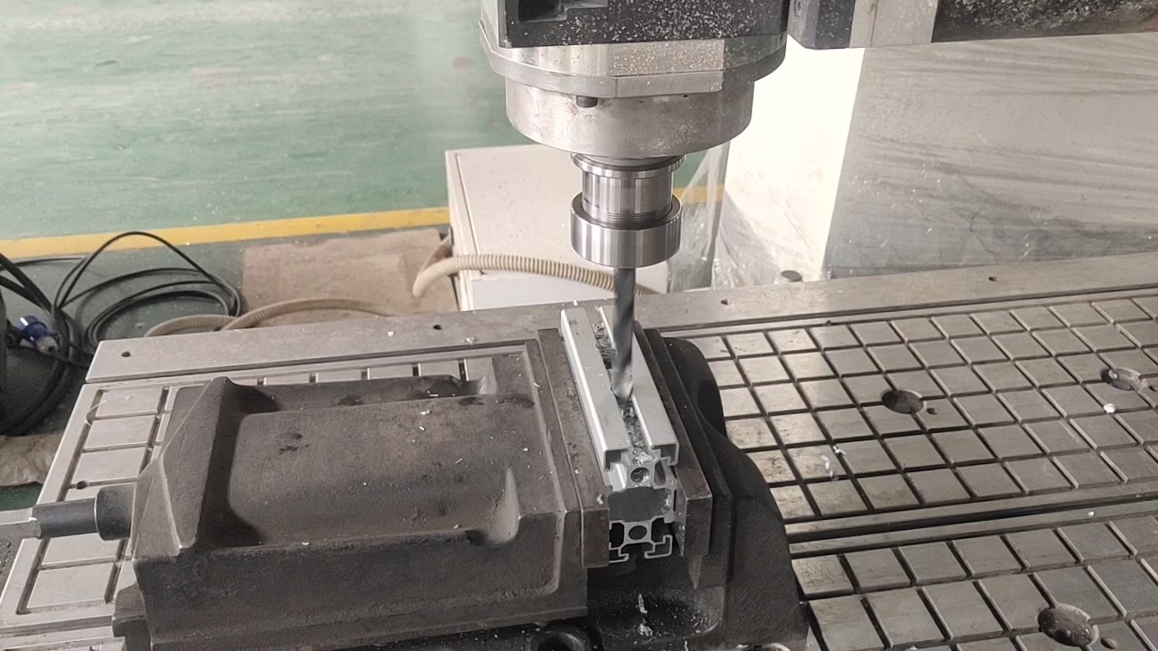
CNC drilling is a subtractive manufacturing process that uses a computer numerical control system to drive spindle rotation, moves the drill bit to cut at preset positions on the workpiece, and produces holes with precise diameter and depth. The machine can automatically control spindle speed, feed rate, retraction height and drilling depth, delivering far higher dimensional consistency in batch production than manual drilling.
It can work as an independent process for mounting holes and clearance holes, or be integrated with milling, turning and tapping operations to complete multi-feature machining in a single setup. This reduces setup errors and improves positional accuracy between different features.
1.2 Core Advantages of CNC Drilling
- High positional accuracy: Coordinates are precisely controlled by the program, ensuring consistent hole positions across batch parts, ideal for multi-hole system machining.
- High machining efficiency: Automatic tool change completes drilling, chamfering and tapping in sequence without repeated manual adjustment.
- Strong process flexibility: Compatible with holes of different diameters and depths, supporting blind holes, through holes, stepped holes and other forms.
- Controllable cost: Standard cutting tools have strong universality, offering outstanding cost-effectiveness for small and medium batch parts.
2. Common Hole Machining Operations and Application Scenarios
Complete hole machining usually consists of multiple processes rather than a single drilling pass. You can match different machining operations according to the function and accuracy requirements of the hole.
2.1 Basic Drilling Operations
Standard drilling: Uses a twist drill to directly form holes, the most basic machining method. It applies to clearance holes, ventilation holes and fluid channels with general accuracy requirements, and usually serves as the pre-drilled hole for subsequent finishing.
Spot drilling: Uses a short center drill to make a positioning indentation before formal drilling, preventing drill deflection and ensuring hole position accuracy. It is especially useful for hard materials, inclined surface drilling or high-precision hole array machining.
Peck drilling for deep holes: When the hole depth exceeds 3 times the diameter, the drill feeds intermittently and retracts repeatedly to break chips and deliver coolant to the cutting zone. This avoids chip clogging that would cause drill wear or rough hole walls.
2.2 Finishing Operations
Reaming: Uses a reamer to remove a small amount of material from a pre-drilled hole, improving diameter accuracy and inner wall smoothness. It is widely used for precision fitting scenarios such as dowel pin holes and bearing fitting holes, with tolerances usually reaching IT7–IT8 grade.
Boring: Uses a single-point boring tool to enlarge an existing hole, correcting straightness and roundness deviations and achieving higher positional accuracy. It suits large-diameter precision holes, bearing holes and hole systems with strict coaxiality requirements.
2.3 Thread and Countersink Operations
Tapping: Uses a tap to cut internal threads in a pre-drilled hole, the standard process for fastener assembly. It delivers low cost and high efficiency for small-batch production of standard threads.
Thread milling: Uses a thread mill to cut threads via circular interpolation. It works better for large-diameter threads, difficult-to-machine materials, thin-walled parts or high-value components. It lowers the risk of tap breakage and enables more precise thread depth control.
Countersinking and chamfering: Countersunk holes accommodate bolt heads to keep fasteners flush with the workpiece surface; chamfering removes burrs at hole edges for easier assembly and guidance. Both can usually be completed in one pass with a dedicated tool.
| Machining Operation | Core Function | Typical Application Scenarios |
|---|---|---|
| Standard Drilling | Creates basic pre-drilled holes | Bolt clearance holes, ventilation holes, fluid channels |
| Reaming | Improves hole diameter accuracy and surface finish | Dowel pin holes, precision fitting holes |
| Boring | Corrects hole shape and position deviation | Bearing holes, coaxial hole arrays, large-diameter precision holes |
| Tapping / Thread Milling | Produces internal threads | Fastener assembly holes, threaded insert pilot holes |
3. Drilling Process Points for Different Materials
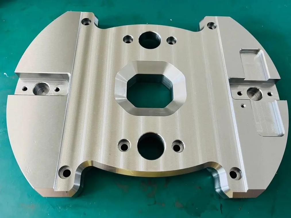
Material hardness, toughness and thermal conductivity directly affect tool selection and cutting parameter settings. Different materials require matching processing strategies.
3.1 Metallic Materials
Aluminum alloys: Excellent machinability and highest drilling efficiency. Pay attention to burr control; optimize clamping methods for thin-walled parts to avoid deformation. High spindle speed with emulsion cooling delivers better hole wall quality.
Carbon and alloy steels: Higher cutting forces and faster tool wear. Adjust feed rate according to material hardness. Ensure sufficient coolant supply during deep hole machining to avoid work hardening.
Stainless steels: Poor thermal conductivity and strong work hardening tendency. Use carbide drills, adopt low-speed and high-feed cutting parameters, and supply sufficient coolant to dissipate heat and extend tool life.
Copper and copper alloys: Soft and sticky material prone to built-up edge. Keep cutting tools sharp. Hole edges tend to form burrs, so arrange a chamfering process to remove sharp edges.
3.2 Non-metallic Materials
Engineering plastics (POM, PEEK, nylon, etc.): Low heat deflection temperature, prone to melting edges during drilling from excessive cutting heat. Use sharp high-speed steel drills, control cutting temperature, and prevent clamping deformation on thin-walled parts. Pre-dry hygroscopic materials before processing.
Composite materials (FR4, carbon fiber sheets): Highly abrasive and cause rapid tool wear, with risks of delamination and edge splitting. Use dedicated diamond-coated drills, run at high speed with low feed rate, and work with dust extraction systems to ensure hole edge quality.
4. DFM Design Guidelines for CNC Drilling
Well-thought-out design is the key to reducing machining costs and improving hole quality. Following these guidelines at the design stage can effectively cut rework and shorten lead times.
4.1 Depth-to-Diameter Ratio
For standard drilling, keep the depth-to-diameter ratio within 3:1. Beyond this range, the process falls into deep hole machining, which requires a peck drilling cycle and brings higher cost and longer cycle time.
For blind holes, reserve space for the drill point at the bottom. Do not mark the effective depth to the very bottom of the hole cone. The pilot hole for threads must be deeper than the effective thread length to leave enough retraction space for the tap.
4.2 Edge Distance and Wall Thickness
Keep the distance from the hole edge to the workpiece side wall at least 1.5 times the hole diameter. Insufficient edge distance will cause material chipping during drilling, reduce thread strength, or even lead to workpiece deformation and cracking.
For thin-walled parts, place holes away from thin-wall areas as much as possible, or increase local wall thickness to prevent workpiece vibration during drilling, which would degrade hole roundness and position accuracy.
4.3 Thread Design Specifications
Drawings must clearly indicate thread specification, pitch, effective thread depth and total hole depth. For blind hole threads, reserve at least 1–1.5 times the pitch as retraction space to prevent tap breakage at the hole bottom.
If the part will undergo surface treatments such as anodizing or electroplating, consider the effect of coating thickness on thread fit in advance and appropriately enlarge the pilot hole tolerance.
4.4 Reasonable Tolerance Setting
General mounting holes can follow standard tolerances without extra finishing operations. Only holes for precision fitting — such as dowel pins and bearing assemblies — need reaming or boring to improve accuracy.
Mark hole position tolerances based on a unified datum system to avoid cumulative assembly errors. Design multi-hole arrays on the same clamping surface as much as possible to reduce position deviation from part flipping.
5. Hole Quality Inspection and Control
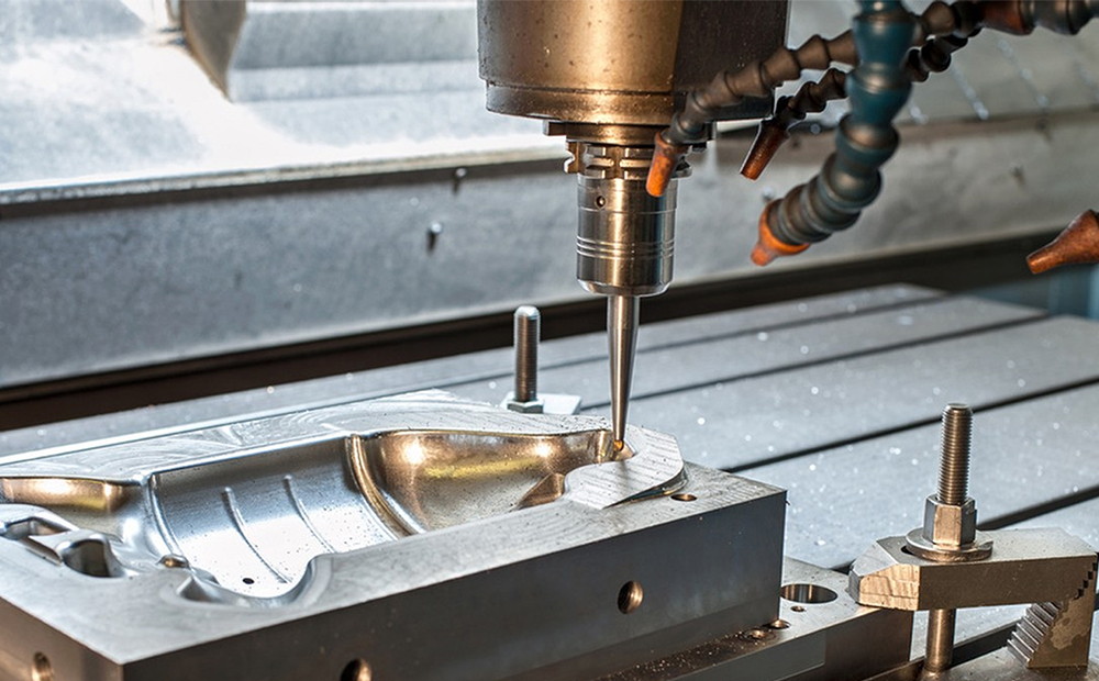
CNC drilling quality inspection covers four core dimensions: dimensional accuracy, position accuracy, thread quality and surface quality.
5.1 Dimensional and Position Inspection
Hole diameter can be quickly checked with plug gauges or internal micrometers. Position accuracy is usually measured by a coordinate measuring machine (CMM) or vision measuring system to verify position degree, coaxiality and other geometric tolerances relative to the datum.
For depth dimensions, use a depth gauge or depth micrometer. For blind holes, focus on verifying that both the effective hole depth and effective thread depth meet drawing requirements.
5.2 Thread and Surface Inspection
Inspect threads with go/no-go gauges. A qualified thread allows the go gauge to screw in smoothly and stops the no-go gauge from fully engaging. Check for defects such as torn threads, stripped teeth and residual chips.
Inspect hole edges and inner walls for burrs, scratches and roughness. For appearance parts and sealing holes, ensure no burrs or flanging at hole openings. For precision fitting holes, confirm inner wall roughness meets specifications.
6. Preparation Checklist for Project Inquiry
To get an accurate quotation and a reasonable process plan, prepare the following materials when submitting an inquiry for CNC drilling projects:
- 2D engineering drawings with complete dimensions, tolerances, datums, thread specifications and technical requirements
- 3D model files in STEP/IGS format for programming and process evaluation
- Material grade and hardness requirements
- Production quantity and delivery time requirements
- Surface treatment and post-processing requirements (anodizing, electroplating, heat treatment, etc.)
- Special inspection requirements for critical holes
7. Frequently Asked Questions
Q: What is the difference between CNC drilling and CNC hole milling?
CNC drilling uses a dedicated drill bit to cut along the axial direction, suitable for standard-diameter round holes with high efficiency and low cost. CNC hole milling uses an end mill to cut via circular interpolation, which can create holes of any diameter and irregular shapes with greater flexibility but lower efficiency. For small-diameter standard holes, the drilling process is always the first choice.
Q: Do all holes need reaming?
No. Standard drilling is sufficient for ordinary clearance holes and mounting holes. Reaming or boring is only necessary when the hole requires precision fitting, such as for positioning pins or bearing assemblies. Over-processing will only add unnecessary costs.
Q: What should be noted for deep hole machining?
The core challenges of deep hole machining are chip evacuation and cooling. Typically, a peck drilling cycle is used: the drill feeds in short increments and retracts repeatedly to break and remove chips, while coolant fully reaches the cutting edge to lower temperature. For extremely high depth-to-diameter ratios, optimize the design first or use dedicated deep hole drilling equipment.
Q: Why do drills break easily when drilling stainless steel?
Stainless steel has poor thermal conductivity, so cutting heat concentrates on the cutting edge. It also has a strong work hardening effect, which accelerates drill wear under improper feed settings. In addition, the high toughness of stainless steel makes chips difficult to break, and clogged flutes will eventually cause the drill to fracture. Optimizing cutting parameters, using application-specific drills and ensuring sufficient coolant can effectively reduce breakage risks.
Summary
CNC drilling is a seemingly basic but critical process that directly affects the assembly reliability of parts. From reasonably planning hole specifications and layout at the design stage, to matching proper tools and process parameters during machining, and then to final quality inspection, every step influences the final cost and product quality.
PartsMastery provides professional CNC drilling and supporting machining services, covering full-cycle needs from prototype development to low-volume production. Our engineering team offers professional DFM manufacturability analysis to help you optimize design, control costs and improve product yield.