






Sheet metal cutting is the foundational first step in any metal fabrication workflow. It defines the maximum possible quality of every downstream stage — from bending and welding to surface finishing and final assembly. Choose an unsuitable cutting method, and you will face unnecessary secondary operations, wasted raw material, and parts that fall out of tolerance before forming even begins.
From on-site repair work with hand tools to high-volume production with CNC equipment, the industry relies on eight core sheet metal cutting processes. Each method has distinct strengths in material thickness, precision, edge quality, and overall cost. Matching the right process to your part requirements is the key to balancing efficiency, quality, and budget.
8 Core Sheet Metal Cutting Methods in Detail
Below is a quick comparison of all eight methods to help you build a preliminary judgment:
| Method | Thickness Range | Typical Tolerance | Edge Quality | Best For | Relative Cost |
|---|---|---|---|---|---|
| Fiber Laser | 0.5–25mm steel | ±0.05mm | Excellent, low burr | Complex profiles, production runs | Low–Medium |
| Plasma | 3–50mm+ | ±0.5–1.0mm | Fair, HAZ + dross | Thick structural plate | Medium |
| Waterjet | 0.5–150mm+ | ±0.1–0.2mm | Excellent, no HAZ | Heat-sensitive alloys, composites | Medium–High |
| CNC Turret Punch | 0.5–6mm | ±0.1mm | Good | High-hole-count panels, volume | Medium (incl. tooling) |
| Shearing | Up to 6mm | ±0.2–0.5mm | Good, slight burr | Straight blanks, high volume | Low |
| Power Tools | Varies by tool | ±0.5–3mm | Rough to good | Field work, one-offs | Low |
| Hand Tools | Up to 22 gauge | ±1.5mm+ | Fair | DIY, thin-gauge trim | Very Low |
| Band Saw / Chop Saw | Bars, tubes, sections | ±1–3mm | Rough | Stock cut-to-length | Low |
1. Fiber Laser Cutting
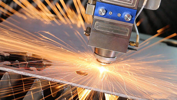
Fiber laser cutting uses a focused high-power beam directed along a CNC-programmed path to melt and vaporize metal. An assist gas blows molten material out of the kerf — typically oxygen for mild steel and nitrogen for stainless steel and aluminum.
The choice of assist gas matters for downstream work. Oxygen-assisted cuts on stainless steel leave a chrome-depleted oxide layer that requires grinding before welding. Nitrogen produces a bright, oxide-free edge ready for TIG welding immediately. Higher per-cut gas cost often pays for itself in saved prep labor.
This non-contact process delivers the tightest precision of all thermal cutting methods. Thin webs between holes and delicate features stay intact, and parts see almost no distortion. No custom tooling is required, and programs run directly from DXF files. This makes fiber laser the default choice for prototypes and short-run parts where punch tooling would not justify its cost.
It does have practical limits. Reflective metals like copper and brass need higher laser power and careful parameter tuning, so not every shop runs them reliably. On steel above 25mm, cut quality and speed drop off sharply, and plasma or waterjet becomes the better option.
2. Plasma Cutting
Plasma cutting passes an electrically ionized gas jet through a constricting nozzle at temperatures above 20,000°C. The arc melts the metal, and the high-velocity gas clears molten material from the cut. It only works on electrically conductive materials — mild steel, stainless steel, and aluminum.
The method defines the speed-to-precision tradeoff. It cuts thick plate faster than laser at a much lower capital cost. The tradeoff is a wider kerf, a visible heat-affected zone, and dross on the cut edge. For any fit-critical surface, secondary grinding is mandatory.
Tolerances sit at ±0.5–1.0mm — an order of magnitude looser than fiber laser. For structural brackets, equipment bases, and construction components, this is often enough. For enclosure panels or parts headed to a press brake with small bend allowance, it usually is not. On thin sheet below 3mm, the HAZ becomes disproportionately large, making plasma a poor choice for light-gauge work.
3. Waterjet Cutting
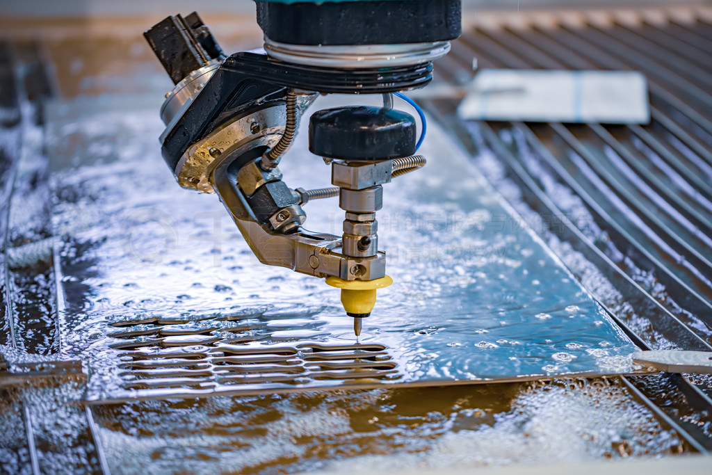
Waterjet cutting forces water at up to 90,000 PSI through a jewel orifice, mixing in garnet abrasive to erode material along a CNC path. It is the only cold-cutting process in common sheet metal fabrication.
Zero heat input means no HAZ, no microstructural changes, and no thermal distortion. This makes waterjet the go-to choice for materials where thermal damage is unacceptable — titanium aerospace brackets, hardened tool steels, Inconel, and multi-layer material stacks. It also cuts non-metal materials like glass, ceramics, rubber, and composites.
Edge quality is excellent — no burr, no oxidation, no hardened edge layer. A waterjet-cut part can go straight to anodizing or welding with no prep work.
The tradeoff is speed and cost. Waterjet cuts 5–10 times slower than fiber laser on equivalent steel thicknesses. Operating costs run higher due to continuous garnet consumption and pump maintenance. It makes sense when material cost or thermal sensitivity justifies the premium; for run-of-the-mill mild steel brackets, laser does the same job faster and cheaper.
4. CNC Turret Punching
CNC turret punching uses a rotating library of standard punch-and-die sets. The CNC positions the sheet under the selected tool, and the punch drives through the material to create holes, slots, and simple profiles in a single stroke.
Its defining advantage over laser is that it does more than just cut. Standard tooling can also form louvers, countersinks, dimples, embosses, and knockouts — features that would require separate operations after laser cutting.
For parts with dense hole patterns — electrical enclosures, chassis panels, bus bars — turret punching delivers a lower cost per hole than laser at production volumes. Modern machines reach 500–1,500 hits per minute for very high throughput.
The limitation is geometry. Punch shapes are limited to the tool library; complex freeform profiles need laser or waterjet. Tooling investment is also the gating factor. Custom shapes carry lead time and cost. For 50 parts with 200 holes each, tooling pays back quickly. For a 5-part prototype run, laser with zero tooling cost is the obvious choice.
5. Shearing (Guillotine Cutting)
Shearing drives a hardened blade pair through sheet metal in a straight line, essentially a giant set of scissors. It is the simplest mechanical cutting method and the cheapest per cut for straight blanks.
There is one hard shape limitation: straight lines only. No curves, no internal cutouts, no custom profiles. Shearing cuts rectangular blanks from larger sheets, preparing stock for downstream bending, stamping, or further precision cutting.
It works on mild steel, stainless steel, aluminum, and galvanized sheet up to 6mm thick. Edge quality is good, with a slight burr on the bottom face that rarely interferes with bending. No heat means no thermal distortion on coated or galvanized material.
At high volume, shearing rectangular blanks is the lowest-cost way to produce starting stock. A fabrication shop processing 500 enclosures a month will shear thousands of panels before those panels ever see a press brake. For one-off complex shapes, shearing is the wrong tool entirely.
6. Power Tools
When a part is on-site and a fabrication shop is not available, power tools do the cutting. Speed and portability come at the cost of precision and edge quality. Three main tools cover most field situations:
- Angle grinder with cut-off disc — the fastest portable method, cuts any thickness and any metal. The edge comes out rough, with burrs, heat discoloration, and slight distortion on thin sheet. Grinding after cutting is routine. Sparks and flying debris make workspace prep and PPE non-negotiable.
- Electric nibbler — punches a series of small overlapping slots to produce a clean, undistorted cut on sheet up to about 18 gauge. It follows curves well and generates no heat or sparks. Waste comes out as small crescent chips, and the cut edge needs almost no cleanup.
- Circular saw with carbide metal blade — handles straight cuts in thicker sheet, 10 gauge and up. A clamped straight-edge guide is essential; without it, the cut wanders. Stick wax lubrication extends blade life on heavier gauges.
None of these tools hold tolerance for production parts. They are field tools, not fabrication equipment. If the part needs ±0.5mm or better, it belongs on a CNC machine in a shop.
7. Manual Hand Tools
Hand tools cut sheet metal the old way — muscle power and leverage. They work when power is unavailable, the cut is short, or the material is thin enough that machine setup would take longer than the cut itself.
Aviation snips use a compound-leverage mechanism and follow a color-coded system: red handles cut left curves, green handles cut right curves, yellow handles cut straight. They work reliably on steel up to about 22 gauge. For aluminum and copper, the usable gauge ceiling is slightly higher because softer metals require less force.
Technique matters more than with machine methods. Closing the blades about 80% per stroke avoids pinching the metal and creating jagged edges. Long, smooth strokes produce a cleaner cut than short, choppy ones. Even with good technique, do not expect better than ±1.5mm accuracy on a straight cut over 300mm.
Hacksaws handle small straight cuts on thicker material, up to about 3mm, where snips cannot generate enough force. The cut is slow, the edge is rough, and it is the last resort when no better tool is available.
Hand tools have one clear place: thin-gauge field work. HVAC ductwork, metal roofing trim, and quick bracket modifications are their sweet spot. For anything that goes into a product drawing with a tolerance callout, hand tools are the wrong answer.
8. Band Saws and Chop Saws
Band saws and chop saws do not cut sheet metal profiles or create part geometries. They cut stock to length — bars, tubes, pipes, and structural sections that feed into later fabrication steps.
A horizontal band saw runs a continuous toothed blade through the workpiece. Blade speed, feed rate, and tooth pitch all affect cut quality. Set correctly, it produces a reasonably square, straight cut on solid bar and tubing. It is slow but consistent, and the standard tool for raw stock prep in fabrication shops.
A chop saw with an abrasive disc cuts structural sections fast. Steel angle, channel, and square tube go through in seconds. The cut is rough, hot, and leaves a burr — fine for stock prep, not for finished part edges. Carbide-tipped dry-cut saws produce a cleaner, cooler cut and have replaced abrasive discs in many shops.
How to Choose the Right Cutting Method
Five factors determine which method fits your project best. Work through them in order to narrow down your options quickly.
1. Material Type and Thickness
This first question eliminates methods immediately. Cutting 20-gauge stainless steel? Tin snips might work; plasma will create a HAZ wider than the part itself. Cutting 15mm mild steel plate? Fiber laser handles it cleanly; shearing does not.
| Material | Up to 1mm | 1–3mm | 3–6mm | 6–12mm | 12–25mm | 25mm+ |
|---|---|---|---|---|---|---|
| Mild Steel | Laser, Punch, Shear | Laser, Punch, Shear | Laser, Plasma, Waterjet | Laser, Plasma, Waterjet | Plasma, Waterjet | Plasma, Waterjet |
| Stainless Steel | Laser, Punch, Shear | Laser, Punch, Shear | Laser, Waterjet | Laser, Waterjet | Waterjet | Waterjet |
| Aluminum | Laser, Punch, Shear | Laser, Punch, Shear | Laser, Waterjet | Laser, Waterjet | Waterjet | Waterjet |
| Copper / Brass | Laser*, Waterjet | Laser*, Waterjet | Waterjet | Waterjet | Waterjet | Waterjet |
*Requires higher laser power and careful parameter tuning — not every shop runs reflective metals reliably.
2. Cut Geometry
Shape and internal features drive your next decision:
- Straight-line cuts with no internal features → shearing is the cheapest option by far.
- Complex external profiles with internal cutouts → laser or waterjet is the right call.
- Dense hole patterns on flat panels → turret punching may beat laser on cost at volume.
3. Precision and Edge Quality
Tighter tolerance and better edge finish come with higher cost, so match the method to the requirement:
- ±0.05mm precision, cosmetic edge, weld-ready surface → fiber laser.
- ±0.1–0.2mm, zero thermal impact, exotic material → waterjet.
- ±0.5–1.0mm, structural use only → plasma.
- Press brake or tight fit-up downstream → laser or waterjet to avoid secondary grinding.
4. Production Volume
Volume changes the cost math entirely. Setup and tooling costs amortize over parts, so what is expensive at low quantity becomes cheap at high quantity.
| Volume | Best Method | Why |
|---|---|---|
| 1–10 parts | Laser, Waterjet, Hand/Power Tools | Zero tooling cost, programming only |
| 10–500 parts | Laser, Waterjet | No tooling lead time, consistent quality |
| 500–5,000 parts | Laser, Turret Punch, Shear | Tooling amortizes; punch wins on high-hole parts |
| 5,000+ parts | Turret Punch, Shear + Laser combo | Full tooling payback, lowest per-part cost |
5. Budget and Lead Time
Capital cost lines are clear. Hand and power tools sit well below the threshold for in-house purchase. Laser cutters, CNC turret punches, and waterjet machines sit well above it for most teams. Most engineering groups use in-house tools for quick modifications and outsource production cutting.
For outsourced work, the lead-time equation flips. Laser cutting from a DXF file can start the same day. Turret punching may need 1–2 weeks if custom tools are required. Shearing is same-day for straight cuts. Waterjet is slower per part, so queue times are often longer.
In-House vs. Outsourced Cutting
Three clear signs mean a job should go to a fabrication shop:
- Tolerances tighter than ±0.5mm. Hand and power tools cannot hold this consistently. Even a well-set-up shear starts to drift above 100 parts.
- Production quantities beyond a handful of parts. Cutting 50 identical brackets with an angle grinder takes hours and produces 50 slightly different parts. A laser cuts them all identical in minutes.
- Edge quality matters for downstream work. A plasma-cut edge that needs grinding before welding adds labor and time. A laser-cut edge goes straight to the welding table.
A shop with in-house fiber laser, press brake, and welding can cut, form, and weld parts in a continuous flow — no shipping partial assemblies between suppliers, no finger-pointing when dimensions are off.
How Cutting Method Affects Downstream Fabrication
The cutting method sets the starting condition for bending, welding, and finishing. The gating question: does the cut part move to the next operation as-is, or does it need secondary work first?
- Laser-cut edge → ready for bending and welding. Square, clean, minimal burr. A mild steel part goes from the cutting table to the press brake with no intermediate step.
- Plasma-cut edge → often needs grinding. The HAZ leaves a hardened edge layer and dross. Welding over it without cleaning produces porosity and weak fusion.
- Waterjet-cut edge → weld-ready on all materials. No HAZ, no hardened layer, no oxidation. Critical for aerospace and medical parts where contamination risk must be minimized.
- Sheared edge → fine for most bending. The slight burr on the bottom face rarely interferes with press brake tooling. Exposed edges may need a quick deburring pass.
- Hand/power tool edges → highly variable. Operator skill determines quality. Plan for deburring and fettling time proportional to the number of cuts.
The cleanest cutting method often reduces total part cost when it eliminates downstream rework. A more expensive cutting process can produce a cheaper finished part when the alternative creates secondary operations. Always total the process cost, not just the cut price.
Conclusion
The right cutting method is a function of material, thickness, geometry, volume, and what happens to the part after cutting. A method that works for a one-off bracket may waste budget on a 5,000-part production run. A method that delivers the lowest per-cut price may create downstream grinding costs that erase the savings.
For most prototype and production sheet metal parts that need tight tolerances and clean edges, fiber laser cutting is the workhorse. It handles most materials and thicknesses, requires no tooling, and produces edges ready for bending and welding.
If you need sheet metal parts cut, formed, and finished, upload your CAD file to PartsMastery for an instant quote. The system generates pricing and a free DFM review that flags bend relief, hole-to-edge clearance, and feature interference before production starts.
Frequently Asked Questions
What is the most precise way to cut sheet metal?
Fiber laser cutting achieves ±0.05mm positional accuracy — the tightest tolerance of all common sheet metal cutting methods. Waterjet follows at ±0.1–0.2mm. Both produce clean, burr-free edges suitable for parts going directly to assembly or welding.
Can I cut stainless steel with tin snips?
Only on very thin gauges — 24 gauge and thinner. Stainless steel work-hardens as it cuts, making each subsequent stroke harder. Even aviation snips rated for 22 gauge mild steel will struggle on stainless at the same thickness. For anything thicker, use a power nibbler or send it to a shop with laser or waterjet capability.
What is the cheapest way to cut sheet metal in production?
For straight rectangular blanks at volume, shearing delivers the lowest cost per cut. For complex profiles at production quantities above roughly 500 parts, CNC turret punching often beats laser on per-part cost when geometry works with standard tooling.
Does laser cutting warp thin sheet metal?
It can, but the effect is minimal compared to plasma. Fiber laser’s small spot size and high speed limit heat input to a very narrow zone. Thin sheets below 1mm may show slight edge distortion; nitrogen assist gas and optimized power settings reduce it further. Waterjet eliminates thermal distortion entirely for the most sensitive applications.
What cutting method works best for aluminum sheet?
Fiber laser with nitrogen assist gas produces the cleanest cut on aluminum up to about 12mm. The nitrogen prevents edge oxidation and leaves a bright, weld-ready surface. Waterjet is the alternative for thicker aluminum or when zero thermal effect is required. Plasma works for structural aluminum parts but produces a rougher edge.