






Standard injection molding typically holds dimensional tolerances around ±0.1 mm, which works for basic housings and non-critical parts. For components that need reliable sealing, precise snap fits, or meshing gear mechanisms, this level of accuracy falls short. Precision injection molding targets tolerances as tight as ±0.02 mm to ±0.05 mm — but true precision means holding that consistency across every shot in a full production run, not just on a single first-article sample.
This guide breaks down the real requirements of precision molding: realistic achievable tolerances by material, core process control practices, critical mold design decisions, and how to evaluate when the added cost of precision manufacturing delivers tangible functional value.
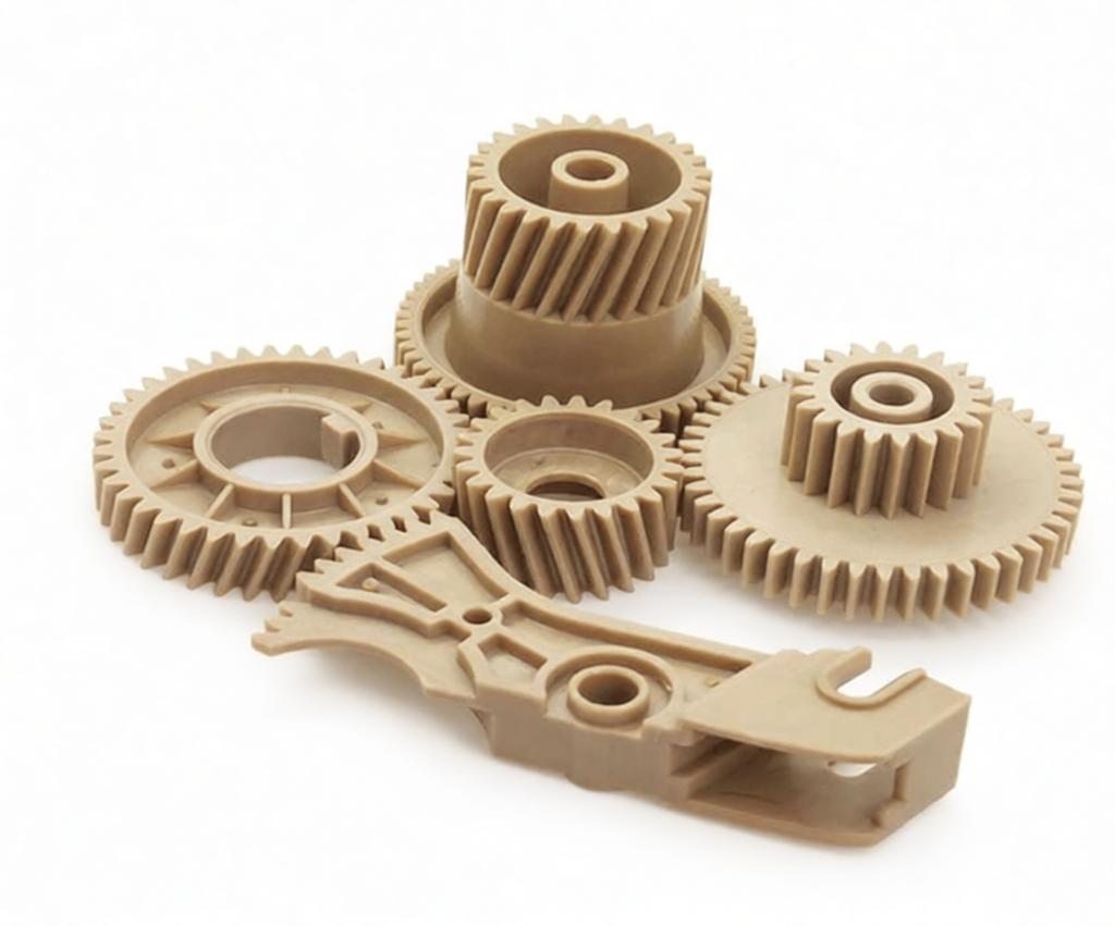
What Separates Precision Molding From Standard Production
Precision injection molding follows the same core cycle as standard molding: melt plastic, inject into the cavity, cool, and eject. The difference lies in how tightly every variable is controlled and monitored throughout the run. Four key areas define precision-grade production.
1. Closed-loop pressure regulation
Standard molding often runs on open-loop timer settings, with no feedback from inside the mold cavity. Precision presses use real-time cavity pressure sensors to dynamically adjust fill speed, pack pressure, and hold duration shot by shot. This ensures the material experiences identical conditions every cycle, even as ambient temperature or raw material batch properties shift slightly.
2. Precision-machined mold alignment
Precision tools are machined to much tighter dimensional tolerances — typically ±0.01 mm on core cavity features — than standard production molds. Ejector pin clearances, slide fits, and parting line flatness are all held to stricter specs. The goal is to eliminate every source of mechanical variation that could add dimensional drift separate from the material’s natural shrinkage.
3. Real-time process monitoring
Every production cycle generates a full set of process data: cavity pressure curves, melt temperature at the nozzle, cooling rates, and injection velocity profiles. Statistical process control tracks these parameters against pre-defined upper and lower limits. When values trend toward the threshold, operators can correct the process before parts fall out of spec, rather than catching defects after the fact.
4. Narrow-band temperature stability
Melt temperature, mold surface temperature, and barrel zone temperatures are all maintained within bands as tight as ±1°C. For engineering resins such as PEEK or LCP, where viscosity shifts dramatically with small temperature changes, this level of control is essential. Standard molding may tolerate swings of ±5°C or more, which leads to visible variation in shrinkage and final part dimensions.
Put simply, true precision is defined by repeatability across thousands of shots, not a single perfect sample. A shop that hits ±0.02 mm on the first part but drifts to ±0.08 mm by the end of a shift cannot deliver production-grade precision molding.
Tolerance Standards and Achievable Limits
Two primary industry frameworks define injection molding tolerances: ISO 20457 and SPI classification grades. Neither is a guarantee on its own — actual capability depends on material choice, part geometry, and process control rigor. In practice, most precision molders publish their own achievable ranges based on equipment and quality systems.
Realistic tolerances by material
Shrinkage rate and shrinkage consistency are the biggest factors in how tight a tolerance can be held. Below is a reference for common injection molding materials under precision production conditions.
| Material | Mold shrinkage rate | Commercial tolerance | Precision tolerance | Notes |
|---|---|---|---|---|
| ABS | 0.4 – 0.7% | ±0.10 mm | ±0.05 mm | Predictable low shrink; baseline for general precision parts |
| Polycarbonate | 0.5 – 0.7% | ±0.10 mm | ±0.05 mm | Dimensionally stable when properly dried; moisture causes splay and dimensional shift |
| POM (Acetal) | 1.8 – 2.2% | ±0.15 mm | ±0.05 mm | High but highly consistent shrink; requires well-vented tooling |
| PA66 (Nylon) | 0.8 – 1.5% | ±0.20 mm | ±0.10 mm | Hygroscopic; absorbs moisture and grows dimensionally after molding |
| PA66 GF30 | 0.3 – 0.6% | ±0.10 mm | ±0.05 mm | Glass fiber reduces shrink; gate placement is critical for weld line strength |
| PEEK | 0.4 – 0.6% | ±0.10 mm | ±0.05 mm | High-temperature engineering resin; requires hardened steel tooling |
| PPS | 0.6 – 1.0% | ±0.10 mm | ±0.05 mm | Low moisture absorption; excellent for chemical-exposed precision parts |
| Unfilled PP | 1.2 – 1.8% | ±0.20 mm | ±0.10 mm | High anisotropic shrink; avoid tight tolerances on long flow paths |
| LCP | 0.1 – 0.3% | ±0.05 mm | ±0.02 mm | Near-zero shrink; top choice for micro-precision components |
Factors that widen tolerance variation
Even with best-in-class process control, certain design choices will increase dimensional variation.
- Uneven wall thickness: Thick-to-thin transitions create differential cooling and uneven shrinkage across the part.
- Dimensions crossing the parting line: Any feature split between mold halves adds alignment error on top of material shrinkage.
- High cavity counts: Multi-cavity tools require perfectly balanced runners to avoid cavity-to-cavity dimensional spread.
- Long flow paths: Pressure drop from gate to end of fill creates uneven shrinkage across the part surface.
Practical tolerance ceilings
There are physical limits no amount of process control can overcome. A ±0.01 mm tolerance on an unfilled PP part with a 200 mm flow path is simply not achievable with injection molding alone. For sub-0.02 mm requirements, secondary CNC machining from a molded blank, or direct machining from solid stock, are often more practical solutions.
Best practices for drawing tolerancing
Avoid over-tolerancing every dimension on your drawing “just to be safe.” Identify the 3 to 5 functionally critical dimensions — those that affect assembly, sealing, or performance — and apply tight tolerances only to those.
Specify Cpk requirements (typically ≥ 1.33 for precision work) for critical features, and define measurement conditions — ambient temperature, humidity, and post-molding conditioning time — especially for hygroscopic materials like nylon.
Material Selection for Precision Applications
Material properties set the baseline for what precision is possible. Optimizing tooling and process will not compensate for a material with inherently unstable shrinkage behavior.
Key properties that drive precision
- Shrinkage consistency: A material with 2% shrink that varies by ±0.1% shot to shot is more precise than one with 0.5% average shrink that varies by ±0.2%.
- Moisture absorption: Hygroscopic materials swell as they absorb ambient moisture, shifting dimensions after molding.
- Thermal expansion: Parts used across wide temperature ranges must account for differential expansion between plastic components and mating metal parts.
- Fillers and reinforcements: Glass fiber, carbon fiber, and mineral fillers reduce overall shrinkage but introduce anisotropic shrinkage and reduce weld line strength.
Amorphous vs. semi-crystalline materials
Amorphous materials such as ABS, PC, and acrylic have more uniform shrinkage and are easier to control for tight tolerances, making them a good starting point for precision projects.
Semi-crystalline materials including PA, POM, PEEK, and PP have higher overall shrinkage but can still deliver precision results with consistent mold temperature control and properly designed cooling systems.
When glass-filled grades make sense
Adding 30% glass fiber to nylon cuts shrinkage roughly in half, significantly improving dimensional stability. However, it comes with tradeoffs: reduced weld line strength, accelerated mold wear requiring hardened steel inserts, and a matte, fiber-visible surface finish.
Material selection reference table
| Application requirement | Recommended material | Rationale |
|---|---|---|
| General precision, moderate cost | ABS or PC | Low predictable shrink; wide availability and proven processability |
| High-temperature precision | PEEK or PPS | Excellent dimensional stability at elevated operating temperatures |
| Micro-precision components | LCP | Lowest shrinkage of any thermoplastic; ultra-fine feature replication |
| Toughness + precision | PC/ABS blend | Balances dimensional stability with impact resistance |
| Chemical resistance + precision | PPS or POM | Resists fuels, solvents, and aggressive chemical environments |
| Medical device components | Medical-grade PC, PEEK, ABS | Biocompatible grades with consistent lot-to-lot properties |
Process Control for Consistent Precision
A modern all-electric press is a prerequisite for precision molding, but the machine alone does not guarantee results. The control system, monitoring practices, and team procedures determine whether a molder can hold tight tolerances across full production runs.
Scientific molding vs. conventional molding
Conventional molding is set by machine parameters — barrel temperature setpoints, injection pressure limits, hold timers. The process is adjusted based on how parts look and feel, with little data on what happens inside the cavity.
Scientific molding focuses on what the plastic actually experiences during the cycle. It uses cavity pressure and temperature sensors to define a reference process signature, then adjusts machine inputs to keep that signature identical shot after shot. This shifts control from the machine’s settings to the material’s actual behavior.
Core tools of scientific molding
- Cavity pressure sensors: Piezoelectric sensors mounted behind ejector pins or directly in the cavity wall capture real-time pressure curves. The shape of the curve reveals incomplete fill, insufficient packing, or abnormal cooling.
- Closed-loop adjustment: The press controller dynamically adjusts injection velocity and pack pressure based on sensor feedback, correcting for small variations before they affect part dimensions.
- Nozzle melt temperature monitoring: Barrel setpoints do not guarantee actual melt temperature. Precision molding measures temperature at the nozzle and adjusts screw recovery, back pressure, and speed to maintain consistent material properties.
Statistical process control (SPC)
SPC connects process data to part quality. For precision molding, the workflow follows these steps:
- Define 3–5 critical part dimensions and their tolerance bands.
- Set upper and lower control limits inside the tolerance band, based on the target Cpk.
- Measure sample parts at defined intervals and plot results on control charts.
- Investigate and correct trends that approach control limits, before parts fall out of specification.
A Cpk of 1.0 means the process spread exactly fills the tolerance band, with no margin for normal variation. Cpk ≥ 1.33 is the standard minimum for precision work, and Cpk ≥ 1.67 is typically required for medical, aerospace, and safety-critical components.
People and systems matter as much as machines
Precision molding is as much a system as it is technology. A top-tier press will not deliver consistent results without documented procedures for every process adjustment, proactive mold maintenance schedules, regular calibration of measurement equipment, and trained operators who follow SPC protocols rigorously.
Mold Design for Precision Manufacturing
The mold is the single largest investment in a precision molding project, and design decisions made at the tooling stage define the long-term dimensional capability of the part.
Tool steel selection
Precision molds require hardened tool steels to maintain dimensional accuracy over hundreds of thousands of cycles. Softer steels and aluminum are unsuitable for high-volume precision production.
| Steel grade | Typical hardness (HRC) | Best for |
|---|---|---|
| P20 | 28 – 32 | Low-volume precision runs; non-abrasive materials |
| H13 | 48 – 52 | High-volume production; glass-filled materials; good thermal fatigue resistance |
| S136 / 420 SS | 50 – 54 | High-polish optical parts; corrosion resistance; medical components |
| M390 | 56 – 60 | Maximum wear resistance; highly abrasive resins; long-run precision tools |
Cooling design: uniformity over speed
Cooling uniformity matters more than cooling speed. If one side of the cavity cools faster than the other, the part will warp toward the hotter side, creating dimensional variation.
For complex part geometries, conformal cooling channels — which follow the shape of the part surface instead of straight drilled lines — dramatically improve temperature uniformity and reduce cycle time. For semi-crystalline materials, consistent mold temperature directly controls crystallization rate and therefore final part dimensions.
Gate design and runner balancing
In multi-cavity tools, balanced runners of equal length and cross-section are required to ensure every cavity fills at the same rate, pressure, and temperature.
Gate size and location directly affect precision. Undersized gates create high shear and localized heating that changes shrinkage behavior; oversized gates slow gate freeze and extend cycle time. Gate location also determines flow direction, which drives anisotropic shrinkage patterns in filled materials.
Parting line and alignment features
Whenever possible, locate critical dimensions entirely on one side of the parting line to avoid adding mold alignment error. When dimensions must cross the parting line, use precision interlocks, taper locks, or wedge locks to minimize mismatch between the two mold halves.
Preventive mold maintenance
Precision molds degrade gradually, not catastrophically. A tool that holds ±0.05 mm at shot 1 may drift to ±0.07 mm by shot 50,000 due to normal wear. A structured maintenance schedule — including vent cleaning, wear surface inspection, ejector pin alignment checks, and periodic cavity dimensional verification — preserves precision capability over the tool’s lifetime.
When Precision Molding Is Worth the Cost
Precision molding costs more than standard production — in tooling, cycle time, material grade, and inspection overhead. The premium is justified only when tight dimensional control delivers measurable functional value.
Applications that require precision
- Sealing surfaces and o-ring grooves: Even 0.05 mm of dimensional error can cause leaks or over-compression of seals.
- Snap-fit assemblies: Narrow interference windows require tight control of hook and catch dimensions.
- Gear trains and mechanical interfaces: Small deviations in tooth profile change backlash, wear rate, and binding risk.
- Optical components and lens mounts: Sub-0.05 mm alignment shifts cause visible optical performance degradation.
- Medical device components: Regulatory requirements demand documented process control and consistent dimensional performance.
When standard molding is the smarter choice
- Cosmetic housings: Most enclosure parts work perfectly well with commercial-grade tolerances and good DFM.
- Non-critical internal features: Ribs, bosses for self-tapping screws, and clearance pockets rarely need precision tolerances.
- First-run prototypes: Validate form, fit, and function with a prototype tool before investing in precision production tooling.
- Low-volume production: For small quantities, CNC machining or a standard mold with secondary operations is often more cost-effective.
Avoid the over-specification trap
The most common and expensive mistake in injection molding is over-specifying tolerances. Every dimension called out at ±0.05 mm instead of ±0.10 mm adds cost to the tool, the cycle, and the inspection plan — even on features where the extra precision does nothing for function.
Before finalizing your drawing, ask: what happens if this dimension is 0.05 mm off? If the answer is “nothing functional,” relax the tolerance. You will reduce cost and lead time with no performance penalty.
Conclusion
Precision injection molding is a systems challenge, not just a machine or material challenge. Tight, consistent tolerances are achievable only when material selection, mold design, process control, and quality systems are all aligned.
For parts that genuinely require sub-0.05 mm dimensional control, precision molding delivers unmatched repeatability at production volumes. For less critical applications, standard molding is almost always the more economical choice.
If you are evaluating a precision injection molding project, you can upload your CAD files to PartsMastery for an instant quote and free DFM review, including tolerance feasibility analysis and material recommendations.
Frequently Asked Questions
What certifications should a precision molder have?
ISO 9001 is the baseline quality management standard. For automotive parts, IATF 16949 is typically required. For medical devices, ISO 13485 is the industry standard. Beyond certificates, look for in-house CMM inspection capability, documented SPC programs, and a tracked mold maintenance system.
How do I communicate precision requirements on a drawing?
Apply tight tolerances only to the 3–5 functionally critical dimensions. Include Cpk requirements for those features, and specify measurement conditions — temperature, humidity, and post-molding conditioning time — especially for hygroscopic materials like nylon.
What is the practical difference between Cpk 1.33 and Cpk 1.67?
Cpk 1.33 means the process spread fits within the tolerance band with roughly 4σ of margin between the process mean and the nearest tolerance limit. Cpk 1.67 provides roughly 5σ of margin, meaning far lower risk of out-of-spec parts over long production runs. Medical and aerospace applications commonly require Cpk ≥ 1.67.
How long does precision tooling take compared to standard tooling?
Precision molds add 2–4 weeks of lead time compared to equivalent standard tools, due to tighter machining tolerances, conformal cooling integration, hardened steel processing, and extensive dimensional verification. Rushing precision tooling often skips verification steps and leads to dimensional issues in production.
Do I need precision molding for prototypes?
Usually not. Prototypes are for validating form, fit, and function, not for confirming long-term production Cpk. Standard prototype molds, 3D printed parts, or CNC machined parts are better suited for early-stage validation. Move to precision tooling only after design freeze.