






As a core forming component in injection molding and die casting tools, the mold core shapes internal part features, recesses, holes, ribs, bosses, threads, and complex internal geometries. Working in tandem with the mold cavity, it directly defines a plastic part’s dimensional accuracy, structural integrity, demolding performance, and production cycle stability.
This guide systematically breaks down the core functions of mold cores, mainstream structure types, material selection standards, key design factors, precision manufacturing workflows, and quality control methods. All in all, it serves as a complete professional reference framework for mold developers, product designers, and process engineers.
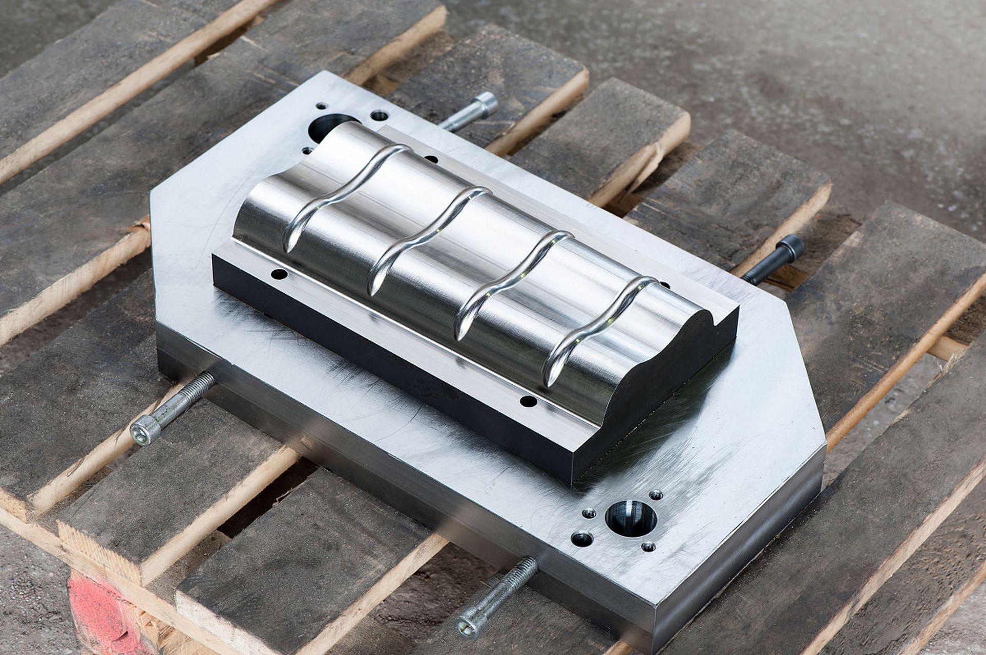
1. Core Functions of Mold Cores and Differences From Mold Cavities
A complete injection mold consists of two main sections: the core side (B side / moving side) and the cavity side (A side / fixed side). The two sections have clearly divided roles and work together to form the final plastic part.
1.1 Functional Positioning Differences
The mold cavity forms the outer surface of the plastic part and directly controls product appearance, texture, branding, and visible details. For this reason, it usually has stricter requirements for surface finish and texture consistency. The mold core, by contrast, forms the internal structure and functional features of the part, including inner walls, bosses, snaps, studs, ribs, undercuts, and threads. Its accuracy directly affects the assembly performance and structural strength of the final product.
1.2 Demolding Logic Differences
As plastic cools and shrinks, it grips tightly around the mold core. For this reason, the core side normally includes an ejection system, and designers intentionally arrange the part to stay on the core side after mold opening for controlled ejection. Poor parting design that causes the part to stick to the cavity side will greatly increase demolding difficulty and may even damage the part during ejection.
1.3 Design Priority Differences
For cosmetic parts, the cavity side prioritizes surface quality and visual effect, while the core side prioritizes structural function, demolding reliability, and cooling efficiency. For precision assembly parts, the core side presents higher technical barriers for dimensional accuracy and structural design, making it the central challenge in mold development.
2. Main Mold Core Structure Types and Application Scenarios
Mold cores come in five main structure types, selected based on the part’s internal complexity, demolding direction, and production volume. Different options vary significantly in manufacturing cost, maintenance difficulty, and forming capability.
2.1 Fixed Mold Cores
Fixed mold cores use a one-piece stationary structure with no relative movement during the molding cycle. They represent the simplest, most cost-effective core solution. Thanks to their few moving parts, they offer high reliability and low maintenance costs with no wear or fit errors from moving components, making them ideal for high-volume stable production.
They work best for standard parts with no side holes, no undercuts, and proper draft angles, such as internal structures for ordinary housings, covers, and base parts.
2.2 Insert Mold Cores
Insert mold cores are modular, independently removable core components mounted onto the mold base via interference fit or locking structures. Their key advantage is that you can replace or repair them individually without scrapping the entire core base. They also support fast switching between multiple product variants on the same platform.
Manufacturers commonly use them for high-wear areas, fine texture / logo regions, structures likely to change in future iterations, and fast-maintenance high-loss sections.
2.3 Side Action Cores (Slider Cores)
Side action cores move perpendicular to the main mold opening direction, driven by angle pins, hydraulic cylinders, or gear mechanisms. They form side holes, side undercuts, snaps, tube connectors, and other features that cannot release along the main parting direction. They expand design freedom for plastic parts but also increase mold complexity, manufacturing cost, and maintenance requirements.
Before adopting side action cores, engineers should first evaluate whether they can simplify the part geometry to avoid the mechanism. When side action is necessary, teams must carefully verify slider stroke, locking force, wear life, and cooling layout.
2.4 Unscrewing and Collapsible Cores
Unscrewing cores release internal thread features via a rotating mechanism to preserve thread accuracy and demolding integrity. Collapsible cores, on the other hand, retract inward after molding to release deep internal undercuts without forcing the part out of shape.
Both solutions work well for bottle caps, tube fittings, fluid connectors, and precision medical components. They come with higher mold costs and require careful design, precision machining, and regular maintenance.
2.5 Casting Cores
Casting cores serve metal casting processes. Technicians place them inside the mold before pouring molten metal, then remove them after solidification to leave internal cavities and flow channels. Common types include sand cores, shell cores, and 3D printed cores, used mainly for complex hollow castings such as valve bodies, pump housings, and manifolds.
3. Mold Core Material Selection Standards and Comparison Table
Mold core material directly determines mold life, machining difficulty, polishing performance, cooling efficiency, and corrosion resistance. The optimal choice depends on four core dimensions: production volume, molding resin properties, accuracy requirements, and budget.
| Material Grade | Core Characteristics | Typical Applications |
|---|---|---|
| P20 Pre-hardened Tool Steel | Excellent machinability, good toughness, moderate cost, usable in pre-hardened state | General consumer plastic injection molds, low-to-medium volume production tools |
| NAK80 Mirror Mold Steel | Outstanding polishing performance, high dimensional stability, high hardness without heat treatment | High-gloss transparent parts, cosmetic packaging, high-appearance plastic part molds |
| S136 Stainless Mold Steel | Strong corrosion resistance, high polishability, excellent rust resistance | Medical-grade molds, optical lenses, molds for corrosive resins such as PVC |
| H13 Hot Work Tool Steel | High hot strength, excellent wear and heat resistance, superior thermal fatigue performance | High-volume production molds, high-temperature engineering resins, glass fiber reinforced materials |
| Aerospace Grade Aluminum Alloy | High machining efficiency, excellent thermal conductivity, light weight | Prototype validation molds, low-volume trial tools, low-precision rapid tooling |
| Beryllium Copper Inserts | Much higher thermal conductivity than steel, exceptional heat dissipation | Local cooling inserts for deep ribs, thick walls, and hot spot concentrated areas |
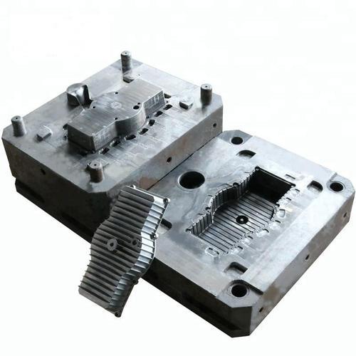
4. Core Control Factors in Mold Core Design
Mold core design directly shapes molding quality, production efficiency, and mold service life. A well-designed core achieves a balanced balance between structure forming, smooth demolding, efficient cooling, and long-term reliability.
4.1 Draft Angle Design
Draft angle is the core parameter that ensures smooth demolding of plastic parts. Insufficient draft causes sticking, drag marks, whitening, and deformation. For standard smooth surfaces, a draft angle of 0.5° to 1.5° is recommended; textured surfaces require 2° to 5° depending on texture depth. Deep ribs, tall bosses, and long inner walls need separate verification to prevent excessive shrink grip force during demolding.
4.2 Shrinkage Allowance
Plastic materials shrink in volume as they cool. Mold core designers must scale dimensions in advance to compensate for this shrinkage and ensure the final part meets target size after cooling. Shrinkage rates vary widely across resins, and glass-filled materials often show anisotropic shrinkage. For precision molded parts, teams refine shrinkage compensation through mold flow analysis, prototype testing, and trial runs before full production.
4.3 Cooling System Layout
Cooling performance on the core side directly affects molding cycle time and part warpage. Cooling channels should sit as close to the forming surface as possible while preserving mold structural strength. For deep cavities, narrow ribs, and areas unreachable by standard channels, engineers use beryllium copper inserts or conformal cooling solutions. Balanced cooling significantly reduces sink marks, warpage, and dimensional deviation while boosting production efficiency.
4.4 Ejection System Design
The ejection system must apply uniform force across the part to avoid ejection deformation, whitening, and cracking. Common ejection methods include ejector pins, ejector sleeves, stripper plates, and pneumatic ejection. Ejection points sit preferentially on high-strength areas such as bosses and ribs, and avoid cosmetic surfaces and precision mating faces whenever possible.
4.5 Undercuts and Internal Features
Internal undercuts, threads, and similar features greatly increase mold complexity. During the design phase, teams should first explore product optimization options by adjusting parting lines or optimizing structure angles to simplify demolding. When complex undercuts are necessary, engineers select side action, unscrewing, or forced demolding solutions based on volume and accuracy requirements.
5. Complete Manufacturing Process for Precision Mold Cores
High-precision mold core manufacturing is a precision machining process that combines multiple technologies. Teams must strictly control accuracy and deformation at every step. A typical workflow follows these stages:
- Material preparation and pre-treatment: Cut raw material to size, and perform pre-stress relief annealing on high-spec materials to reduce later machining deformation.
- Rough machining: Remove most excess material quickly via CNC milling, leave appropriate finishing stock, and complete basic structures such as cooling channels and mounting holes.
- Heat treatment: Perform quenching and tempering per material specifications to reach target hardness and toughness; apply additional stress relief after heat treatment to stabilize dimensions.
- Semi-finishing and finishing: Use high-speed milling and multi-axis machining centers to finish forming surfaces, control dimensional tolerances and surface stock; round core pins, sleeves, and other rotational parts finish via CNC turning.
- Specialty machining: Process deep narrow slots, sharp corners, and fine textures unreachable by standard cutting tools via sinker EDM and wire EDM to preserve feature accuracy.
- Grinding, polishing and surface treatment: Use grinding to ensure flatness, parallelism, and fit accuracy on mating surfaces; apply mirror polishing or texture etching as required; high-spec molds may add nitriding, PVD coating, or other surface treatments for better wear and corrosion resistance.
- Final inspection and assembly: After full-dimensional inspection passes, complete assembly and debugging of inserts, sliders, ejector pins, and other components.
6. Key Quality Inspection Indicators for Mold Cores
Mold core accuracy transfers directly to every molded part, so pre-assembly quality inspection is a critical step in mold quality control. The core inspection items fall into four categories:
6.1 Dimensional Accuracy Inspection
Technicians use CMMs, micrometers, height gauges, and pin gauges to check core depth, hole position accuracy, boss dimensions, thread size, mating face tolerances, and other critical features. For precision mold cores, key dimensional tolerances must stay within ±0.005 mm to guarantee assembly fit precision.
6.2 Surface Quality Inspection
Inspect forming surfaces for roughness, polishing texture, tool marks, etch quality, scratches, and pits. Cosmetic and transparent part mold cores must meet specified polishing grades, and functional surfaces must meet roughness requirements for demolding and mating performance.
6.3 Hardness and Assembly Inspection
Use a hardness tester to verify surface hardness after heat treatment and confirm hardness uniformity meets design requirements. Assembly inspection checks the fit clearance between the core and cavity, inserts, sliders, ejection system, and cooling system to prevent flash, misalignment, wear, or mold damage.
6.4 Trial Mold Validation
Trial molding serves as the final real-world verification step. It evaluates filling, cooling, demolding, dimensional accuracy, and surface quality under actual production conditions. Teams then iterate and optimize core dimensions and process parameters based on trial results until the tool meets mass production standards.
7. Common Mold Core Failure Issues and Solutions
Mold cores develop various failure issues during long-term mass production. Most of them are preventable through design optimization, proper material selection, and process adjustment.
7.1 Part Sticking
Causes: Insufficient draft angle, excessively rough surface, high shrinkage rate, unbalanced ejection layout, excessively deep ribs.
Solutions: Increase draft angle, improve core surface polish, optimize ejection point placement and force balance, adjust molding process parameters, and simplify structures when necessary to reduce demolding resistance.
7.2 Surface Wear
Causes: Abrasive effect of glass fiber reinforced resins, high number of production cycles, insufficient material hardness, poor surface lubricity.
Solutions: Select harder mold steel, add PVD coating or nitriding surface treatment, use replaceable inserts in high-wear areas, and optimize molding parameters to reduce erosion wear.
7.3 Corrosion
Causes: Decomposition of corrosive resins, humid storage environments, rust in cooling water channels.
Solutions: Use stainless steel grades such as S136 for corrosive resins, apply protective coatings to mold surfaces, perform proper rust prevention maintenance after production, and clean cooling channels regularly to prevent rust.
7.4 Dimensional Deviation
Causes: Insufficient machining accuracy, heat treatment deformation, unbalanced cooling, mismatched shrinkage compensation, wear during production.
Solutions: Optimize machining processes and heat treatment procedures, improve cooling system design, refine shrinkage compensation through trial molding, and inspect and repair mold core wear on a regular schedule.
8. Key Industry Application Scenarios
Mold cores see wide use across all industries that rely on injection molding or casting. Different industries impose very different requirements for core accuracy, material, and service life.
- Automotive and new energy: Used in molds for interior parts, structural brackets, connectors, and battery components, requiring long service life, high stability, and dimensional consistency.
- Electronics and 3C: Used in molds for precision housings, connectors, buttons, and battery compartments, with extremely strict requirements for surface quality and fine structure accuracy.
- Medical and life sciences: Used in molds for medical consumables, surgical instrument components, and testing equipment parts, requiring medical-grade materials, high polishing precision, and sterilization corrosion resistance.
- Industrial automation: Used in molds for equipment housings, cable guides, fixtures, and sensor housings, with a focus on structural strength and mass production stability.
- Aerospace: Used in molds for lightweight structural parts and precision fluid components, with stringent requirements for material performance and dimensional reliability.
Frequently Asked Questions
Q1: How do I decide between a simple mold core and a complex side action mechanism?
If all internal features of the plastic part can release smoothly along the main mold opening direction, a standard fixed mold core will suffice. If the part has side holes, internal undercuts, or internal threads perpendicular to the opening direction, you will need a complex solution such as a side action core, unscrewing core, or collapsible core, selected based on feature depth and accuracy requirements.
Q2: What materials work best for high-volume production mold cores?
For high-volume mass production molds, hardened tool steels such as H13 and S136 are usually the first choice. When molding glass fiber reinforced materials, you should upgrade the material grade or add surface coatings. When molding corrosive resins, stainless steel grades are the preferred option.
Q3: What processes are mainly used for precision mold core and insert machining?
Precision mold core machining is based on multi-axis CNC milling, paired with CNC turning for main body structures. Special features such as deep narrow slots and sharp corners are completed via EDM and slow-feeding wire cutting. Finally, precision grinding and polishing ensure dimensional and surface accuracy. For complex cores, manufacturers commonly use a combined CNC + EDM process to balance efficiency and precision.
Conclusion
All in all, the mold core is the central component of a mold system that determines internal structure accuracy, demolding reliability, and production efficiency. Its design and machining quality directly shape the final performance of plastic parts and the stability of mass production. An excellent mold core solution requires precise coordination across the entire workflow, from structural design and material selection to machining process and quality control.
PartsMastery provides precision machining services for high-accuracy mold cores, mold inserts, and custom mold components, covering the full lifecycle from prototype development to production-grade tooling. We are equipped with multi-axis machining centers, slow-feeding wire EDM, sinker EDM, and precision inspection equipment, capable of delivering machining accuracy down to ±0.005 mm with support for various mold steels, stainless steels, and special alloys. Simply send us your 3D drawings and technical requirements, and our engineering team will develop an optimized machining solution for your project.