






CNC plastic machining is one of the core processes in precision manufacturing, widely used in electronics, automation modules, medical devices, automotive components and other industries. Beyond dimensional accuracy and surface finish, tool chatter is a critical factor that defines the quality of plastic parts. It not only leaves irregular chatter marks on workpiece surfaces, but also undermines dimensional stability, accelerates tool wear, and drives up rework and scrap costs.
Compared with metals, plastics have fundamental differences in hardness, elastic modulus, and thermal conductivity. Cutting properties vary drastically across different plastic types, so a one-size-fits-all parameter set never works. Only by optimizing cutting solutions based on material properties and systematically adjusting tooling and processes can manufacturers minimize chatter while improving machining efficiency. This guide explains proven solutions for tool chatter in CNC plastic machining across four dimensions: root causes, parameter tuning, tooling upgrades, and process control.
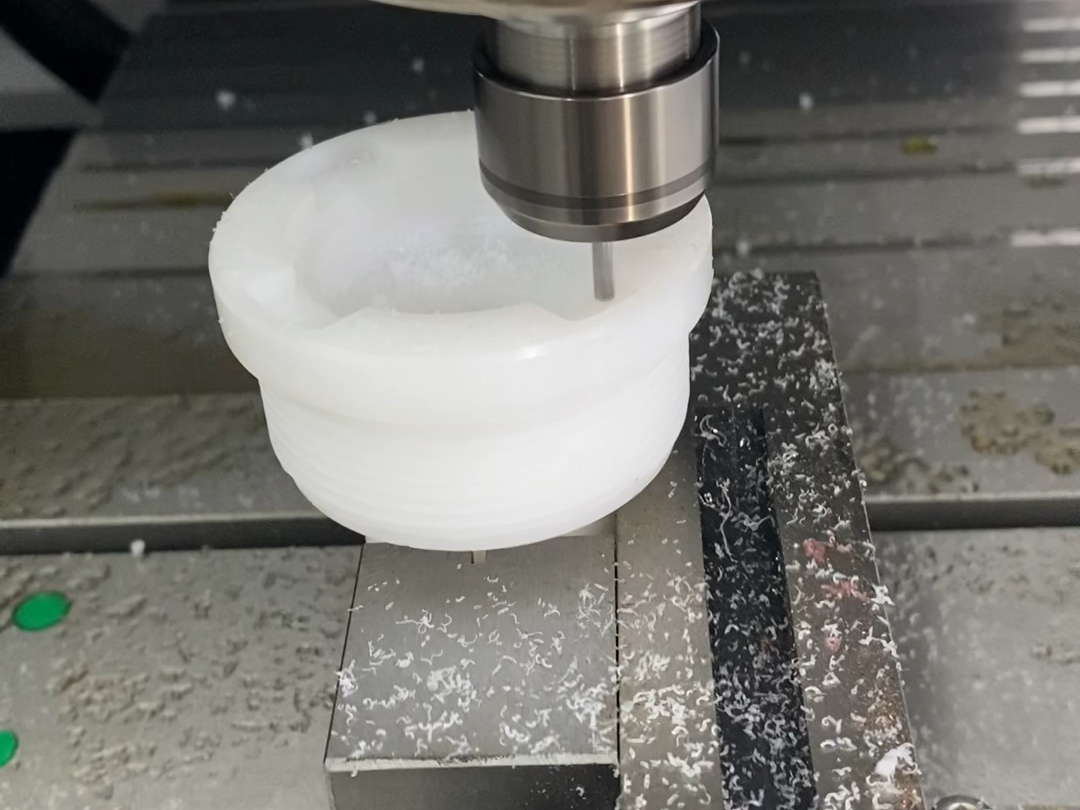
1. Core Causes of Tool Chatter in CNC Plastic Machining
Mechanically speaking, chatter is a self-excited vibration caused by the coupling of cutting force fluctuations and the rigidity of the machine-tool-workpiece system. The inherent properties of plastics make this problem far more common than in metal machining, with three main categories of triggers.
1.1 Viscoelasticity and Low Stiffness of Plastic Materials
Generally, the elastic modulus of plastics is only 1/50 to 1/200 that of metals, giving them pronounced viscoelastic characteristics. They deform instantly under cutting forces and spring back elastically when the force is removed. This dynamic deformation easily couples with cutting frequency to form persistent chatter marks. Softer, tougher plastics show stronger deformation and springback effects and carry a higher chatter risk.
Different plastics show varying vibration tendencies:
- PE (polyethylene) has high softness and large deformation during cutting
- PP (polypropylene) features obvious elasticity and strong springback effects
- PA (polyamide) absorbs moisture, so its stiffness fluctuates with ambient humidity
- UHMW-PE has extremely high toughness, causing continuous fluctuations in cutting resistance
For parts with thin walls, large unsupported spans, or long overhang features, material deformation becomes even more pronounced. For example, when machining a 2mm thin plastic sheet, insufficient bottom support causes the material to bend repeatedly as the tool passes, eventually creating continuous, regular chatter marks.
1.2 Mismatched Cutting Parameters
First of all, the match between spindle speed, feed rate, and cutting depth directly determines cutting stability. Improper settings for any parameter will trigger chatter.
On one hand, excessively high spindle speed increases cutting frequency and generates large amounts of localized cutting heat. Plastics conduct heat poorly, so heat builds up quickly and softens the surface layer, further reducing rigidity and causing cutting stability to collapse. On the other hand, too low a feed rate prevents continuous cutting; the tool slips and rubs against the workpiece surface, creating a friction-slip cycle that induces high-frequency micro-vibration. Finally, excessive cutting depth spikes cutting load instantly, exceeding the rigidity capacity of the machine-tool system and causing overall vibration.
Notably, parameter tolerance varies greatly by material. For example, POM works well with high-speed cutting and has a wide parameter window, while PC is heat-sensitive — too high a speed easily causes stress marks and chatter.
1.3 Insufficient Rigidity of the Tool-Machine System
Furthermore, declining rigidity of the tool system is the most direct mechanical cause of chatter. From a mechanical perspective, doubling tool overhang reduces bending rigidity to 1/8 of the original value, so deflection under cutting force increases dramatically. Plastic machining also requires extremely sharp cutting edges; once edges wear and dull, cutting resistance rises sharply and breaks the cutting balance directly.
Besides that, loose tool holders, reduced spindle runout accuracy, and increased spindle clearance all amplify small vibrations into visible chatter. Many vibration issues that seem like machine faults actually stem from mismatches between tool condition, clamping rigidity, and machining parameters.
2. Precise Parameter Tuning for Fast Vibration Suppression
Plastic machining is highly sensitive to cutting speed, load level, and chip evacuation efficiency. When chatter occurs, adjusting parameters to move out of the vibration range quickly is the most efficient fix.
2.1 Avoid Resonance Zones With Dynamic Spindle Speed Adjustment
In many cases, persistent chatter does not come from a speed that is too high or too low. It happens because the current speed matches the natural frequency of the machine-workpiece system and triggers resonance. Blindly increasing or decreasing speed may not help. The correct approach is to fine-tune spindle speed by ±10% to 20% to shift the cutting frequency out of the resonance band.
Practice shows that each material has its own stable speed range:
- Easy-to-machine materials like POM and ABS work well with medium to high speeds for better efficiency
- Heat-sensitive materials like PC and acrylic need upper speed limits to avoid heat buildup and softening
- Glass fiber reinforced materials require moderately lower speeds to reduce impact wear on tools
For stable mass production, it is recommended to calibrate the optimal speed range through trial cutting instead of using a universal parameter table. This usually delivers a more stable cutting state.
2.2 Match Feed Rate and Cutting Depth for Continuous Cutting
In addition, feed rate and cutting depth must be adjusted together. The core principle is to keep the tool in continuous cutting mode and avoid the unstable cycle of alternating friction and cutting.
Too low a feed rate makes the cutting edge slip and rub on the material surface, which not only causes high-frequency vibration but also melts material and causes tool buildup due to accumulated heat. Too fast a feed rate spikes cutting force instantly and exceeds the system’s rigidity capacity. Cutting depth follows the same logic: too large a depth causes heavy-load vibration, while too shallow a depth creates “rubbing” effects that also damage stability.
For large, thin-walled, or irregular plastic parts, a multiple-light-cut strategy is recommended: remove stock in layers to control single-cut load. This reduces workpiece deformation and significantly improves cutting stability.
2.3 Strengthen Chip Management to Eliminate Secondary Vibration Sources
Plastic chips are mostly long filaments, completely different from the broken chips produced in metal machining. If chips are not evacuated in time, they wrap around the tool or accumulate in the cutting zone. This causes fluctuating cutting resistance and rapid heat buildup, which in turn trigger chatter.
Common chip evacuation optimization solutions include:
- Real-time compressed air blowing to remove chips and carry away cutting heat at the same time
- Vacuum chip extraction systems that continuously suction filamentous chips
- Optimized flute geometry for smoother chip flow
Keeping the cutting zone clean ensures the tool always operates under stable cutting conditions and greatly reduces sudden vibration caused by tangled or clogged chips.

3. Upgrade Tool and Fixture Rigidity to Reduce Vibration at the Source
Parameter adjustments only solve chatter in some scenarios. If tool and workpiece clamping rigidity is insufficient, vibration problems will keep coming back. Upgrading the tooling system is the fundamental solution to chatter.
3.1 Select Application-Specific Tools for Plastic Machining
Tools designed for plastic machining follow completely different design logic than metal cutting tools. The core requirements are low cutting resistance, smooth chip evacuation, and anti-stick properties.
Recommended tool features include:
- Sharp cutting edges to reduce cutting extrusion and deformation
- High rake angle design to lower cutting resistance and material compression
- Single-flute or double-flute end mills with ample chip space and less heat buildup
- Highly polished flutes to prevent plastic chips from sticking to the tool
For glass fiber or carbon fiber reinforced plastics, tool wear speeds up dramatically. Wear-resistant carbide tools, or even diamond-coated tools, are better choices to maintain edge sharpness stability and reduce vibration from rapid tool wear.
3.2 Improve Workpiece Clamping and Support to Reduce Deformation
Plastic parts are lightweight and prone to deformation, so their clamping stability is far lower than metal workpieces. Much chatter essentially comes from workpiece displacement and vibration under cutting force. Choose a clamping solution that matches the part geometry:
- Flat parts: Use vacuum chucks for uniform force and no clamping deformation
- Regular rotary parts: Custom soft jaws to increase clamping contact area
- Thin-walled, long-span parts: Add multi-point auxiliary supports to eliminate unsupported areas
- Irregular parts: Design dedicated positioning fixtures for reliable location and clamping
Increasing support area and distributing cutting forces significantly reduces the workpiece’s own deformation vibration and improves machining stability.
3.3 Control Tool Overhang Length to Boost System Rigidity
Tool overhang is the most overlooked factor that has an enormous impact on rigidity. When machining deep cavities or narrow slots, operators often extend tool overhang for clearance, but this sacrifices rigidity drastically.
Optimization principles:
- Minimize tool overhang as long as the machining depth requirement is met
- Prefer larger-diameter tool holders for higher basic bending rigidity
- Use high-precision clamping solutions (such as shrink-fit or hydraulic holders) to eliminate clamping clearance
This benefit is even more noticeable in plastic machining than in metal work, because even tiny tool deflection shows up as surface chatter marks and burrs on plastic parts.
| Material Type | Core Cause of Vibration | Parameter Optimization Direction | Tooling & Fixture Focus |
|---|---|---|---|
| Soft plastics (PE / PP) | Material deformation and springback | Medium-high speed, moderate feed, ensure continuous cutting | Reinforced support, larger clamping area |
| Heat-sensitive plastics (PC / acrylic) | Heat buildup softening + stress cracking | Limit upper speed, avoid heat accumulation | Sharp high-rake tools, reduce extrusion |
| Reinforced plastics (PA / glass-filled) | Fast tool wear + fluctuating resistance | Moderate speed, controlled feed per tooth | Wear-resistant carbide tools, regular edge checks |
| POM | Resonance zone triggering | Wide parameter window, prioritize resonance avoidance | Standard tooling works well, excellent stability |
4. Full-Process Optimization for Long-Term Chatter Prevention
To achieve consistently stable plastic machining quality, manufacturers cannot focus only on single-operation parameter tuning. They must integrate chatter prevention logic into the entire manufacturing workflow to reduce the probability of chatter at the source.
4.1 Separate Roughing and Finishing With Stress Relief Steps
Internal residual stress releases continuously during cutting of plastic parts. If finishing follows roughing immediately, stress redistribution causes micro-deformation of the workpiece. This not only hurts dimensional accuracy but also breaks cutting balance and triggers chatter.
Recommended standard process flow:
- Roughing: Remove most stock quickly, leave finishing allowance
- Stress relief: Allow several hours of resting time for full stress release
- Semi-finishing: Correct deformation and get close to final dimensions
- Finishing: Light cut depth, high feed, ensure surface quality
Especially for large, complex, or uneven-walled plastic parts, separating roughing and finishing significantly reduces deformation and chatter risks. It is a widely proven high-efficiency solution in the industry.
4.2 Customize Machining Strategies for Each Material Property
There are many types of plastics, each with very different cutting behavior. A universal machining strategy will inevitably cause stability issues. Build a dedicated process package for each material:
- POM has excellent machining stability, so prioritize efficiency with high-speed, high-feed solutions
- PA absorbs moisture easily, so control ambient humidity and pre-dry the material
- PC has high heat sensitivity, so strictly control cutting heat and use efficient chip evacuation and cooling
- PVC is relatively easy to machine, but monitor surface finish and keep edges sharp
Matching the process to material properties eliminates most unnecessary vibration issues and enables stable mass production.
4.3 Establish In-Process Inspection for Early Intervention
Chatter does not appear without warning. Increasing surface roughness, deeper tool marks, and more edge burrs are all early signs of worsening vibration. If not addressed promptly, they quickly turn into batch quality problems.
During production, inspect four items regularly:
- Workpiece surface quality and mark patterns
- Dimensional accuracy stability of critical features
- Tool edge wear and chip buildup conditions
- Reliability of workpiece clamping and support
Catching anomalies early and making adjustments avoids rework for entire batches. Accumulating process data for different materials and structures also helps build a standardized chatter-prevention process library over time.
5. Frequently Asked Questions
Do I always need to replace the tool when chatter occurs in CNC plastic machining?
Not necessarily. Tool wear is only one common cause of chatter, not the only one. Spindle speed falling into a resonance zone, too low feed rate, unstable workpiece clamping, excessive tool overhang, and poor chip evacuation can all cause obvious vibration. If the cutting edge remains sharp, you should first adjust machining parameters and improve clamping and chip evacuation before considering a tool change. Tool replacement delivers the most direct improvement only when edges are chipped, severely worn, or flutes are heavily clogged with built-up material.
How can I effectively reduce vibration when machining thin-walled plastic parts?
The core cause of chatter in thin-walled parts is insufficient workpiece rigidity and easy deformation under cutting force. The solution has three parts. First, reinforce support: use vacuum suction plus multi-point auxiliary supports to minimize unsupported areas. Second, reduce cutting force: adopt a layered light-cut strategy to reduce single-cut load, paired with sharp high-rake tools. Third, optimize tool paths: use climb milling to control cutting force direction and avoid impact on the workpiece.
How do I control tool chatter in plastic machining stably over the long term?
Long-term stable control requires a systematic solution, not one-time parameter adjustments. First, build standard process parameter packages for different materials, defining recommended ranges for speed, feed, and cut depth. Second, standardize tool selection and wear management rules with clear replacement cycles. Third, optimize clamping solutions and create standard fixture designs for typical part structures. Finally, set up in-process inspection and quality traceability mechanisms for continuous iteration. PartsMastery has extensive proven expertise in precision CNC plastic machining, delivering full-process stable solutions from DFM optimization to mass production for various part scenarios.
Conclusion
Tool chatter in CNC plastic machining results from the coupling of material properties, cutting parameters, tooling rigidity, and process flow — but it is not an unsolvable problem. It does not require extreme adjustments in a single dimension; it requires systematic matching and optimization.
Starting from an understanding of material properties, precisely matching cutting parameters, upgrading tool and clamping rigidity, and building a vibration-prevention system through full-process design — most chatter problems can be effectively controlled with these steps. This not only eliminates surface chatter marks, burrs, and dimensional deviations, but also extends tool life, improves machining efficiency, and lowers overall production costs.
As precision manufacturing requirements keep rising, demands for surface finish, dimensional tolerances, and consistency of plastic parts continue to grow. Delivering high-quality CNC plastic machining requires both rich on-site experience and a standardized process system, strict in-process inspection, and continuous iterative optimization. With years of technical accumulation in precision plastic machining, PartsMastery can customize dedicated process solutions based on material properties and part structures, ensuring stability and consistency in mass production.
Article Tags: CNC plastic machining, tool chatter reduction, precision plastic machining, CNC machining process, surface finish optimization