






The long-term reliable operation of industrial automation equipment is built on the precision manufacturing and consistent fit of every single component. During continuous system operation, even minor dimensional deviations in one part can trigger cascading issues such as assembly binding, operational noise, and reduced positioning accuracy. In severe cases, they can even delay the delivery timeline of the entire machine.
For automation equipment manufacturers, high-quality CNC machining services are never simply about producing parts to drawing specifications. The core value lies in the ability to consistently deliver dimensionally consistent, assembly-ready components that support a smooth workflow from prototype validation to full-scale mass production.
PartsMastery specializes in precision component manufacturing for the industrial automation sector. With an assembly-focused approach, we provide custom CNC machining services for a full range of parts including mounting plates, supports, shafts, and transmission components.
1. Three Core Issues That Most Impact Assembly in Automation Part Machining
Automation equipment components work alongside standard parts such as linear guides, motors, cylinders, and bearings. As a result, a single part that passes dimensional inspection may still fail in assembly. In actual production, three categories of issues cause the majority of assembly failures.
1.1 Hole Pattern System Deviation
Mounting holes, locating holes, and threaded holes are the core positioning features of automation parts. Their value lies not in single bore tolerance, but in the positional relationship and fit accuracy of the entire hole pattern.
Positional deviation of locating holes directly defines the installation datum of a component. Even a tiny offset can cause overall misalignment of connected mechanisms and degrade equipment operational accuracy. Individual bores may meet tolerance, but a shifted hole pattern will prevent alignment with standard parts such as guides and motor bases. Insufficient effective thread depth, poor thread form, or burrs around holes will result in inadequate fastener locking and loosening during operation.
1.2 Thin-Wall and Slender Part Deformation
Automation equipment widely uses thin aluminum plates, long support beams, and lightweight connection structures to reduce moving mass. These parts have low rigidity, so clamping force, cutting stress, and residual stress release can easily cause deformation. This leads to a common issue: parts measure correct when clamped, but go out of tolerance once unclamped.
Excessive clamping force creates elastic deformation in the workpiece, which springs back after release and causes dimensional shift. Removing too much material in a single cut disrupts thin-wall structural stability and triggers warping. Slender parts with large overhang and no support suffer from increased cutting vibration, making dimensional accuracy and surface quality hard to maintain.
1.3 Poor Dimensional Consistency Across Batches
Automation equipment projects typically progress from prototype to low-volume runs, then to regular mass production. Producing one good part is rarely the biggest challenge. The real test is delivering dozens or hundreds of parts with consistent dimensional results.
Tool wear, fixture repeatability, and machine state drift all gradually affect machining outcomes. Final inspection alone cannot control these issues at the source. Instead, stable process control is required for reliable batch production.
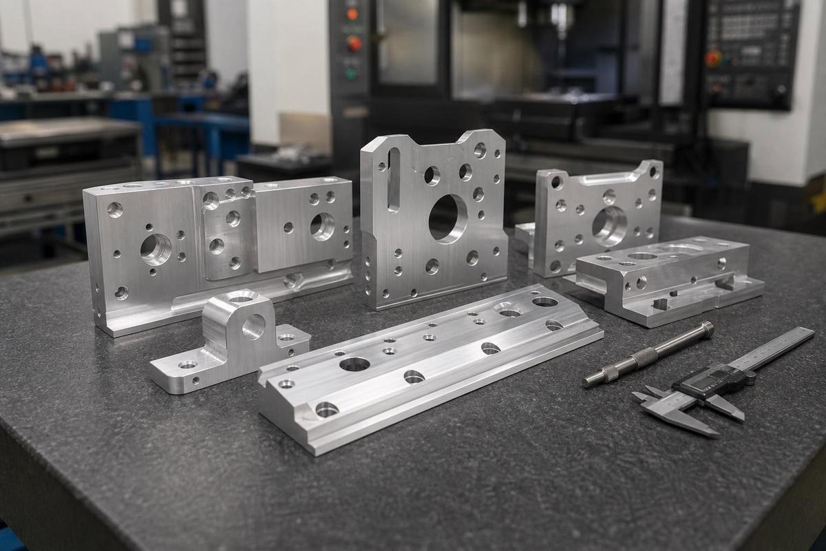
2. Machining Priority Management for Different Automation Part Categories
No universal machining solution works equally well for all parts. Different part types have different core control priorities. Allocating precision resources based on need balances both quality and production cost.
2.1 Mounting Plates and Base Plates: Flatness and Hole Position Are Critical
Mounting plates and base plates serve as the installation foundation for entire automation systems. They carry linear guides, motors, support columns, and other components. An uneven base surface or inaccurate hole positions will cause installation deviation of all upper-level components.
For these parts, key controls include large-surface flatness, hole pattern positional accuracy, and datum surface perpendicularity. Stress release must be controlled after heavy material removal to avoid warpage. Additionally, dimensional impacts from surface treatments such as anodizing and electroplating must be factored into process planning in advance.
2.2 Connection Blocks and Supports: Fit Accuracy and Perpendicularity First
Connection blocks and support seats sit between two mechanisms, transmitting force and positioning components. Issues with these parts rarely come from individual dimensions. More often, they stem from the relative positional accuracy of the two mating surfaces after assembly. Excessive clearance causes vibration and noise, while insufficient clearance causes motion binding.
During machining, focus must be placed on hole positional accuracy, mating surface perpendicularity, and fit dimensional tolerances. This ensures proper fit and alignment between connected mechanisms.
2.3 Shafts and Moving Components: Geometric Tolerances Define Performance
Rotary shafts, guide shafts, and drive pins place extremely high demands on diameter tolerance, concentricity, runout, and surface roughness. These factors directly affect equipment running smoothness and service life. If subsequent heat treatment or surface finishing is required, post-process dimensional changes must be calculated in advance.
| Categoría de piezas | Puntos clave de control del mecanizado | Core Assembly Objective |
|---|---|---|
| Mounting Plate / Base Plate | Flatness, hole pattern position, datum perpendicularity | Stable, deviation-free equipment base installation |
| Connection Block / Support Seat | Hole position accuracy, mating surface perpendicularity, fit dimensions | Smooth connection with proper clearance between mechanisms |
| Shaft / Drive Pin | Diameter tolerance, concentricity, runout, surface roughness | Smooth, binding-free motion of moving components |
| Thin-Wall Bracket / Connector | Deformation control, geometric tolerance, burr removal | Proper assembly of lightweight structures without deformation |
3. Full-Process Control Methods to Reduce Rework From Prototype to Production
Automation equipment projects operate on tight delivery schedules. The biggest risk is not failing to produce a prototype, but discovering dimensional issues in mass production that cause extensive rework and delivery delays. A three-stage control approach can significantly reduce production rework rates.
3.1 Prototype Stage: Physical Assembly Validation Over Pure Dimensional Inspection
A part that passes dimensional inspection may still cause assembly issues when installed in the actual machine. This happens because individual part tolerances can stack up to exceed acceptable limits. For this reason, prototype validation must go beyond inspection reports and include full physical assembly testing.
Verify hole pattern compatibility with standard parts to identify accumulated dimensional deviation. Check fit clearances of moving components to ensure no binding and excessive play. Confirm final dimensions and appearance after surface treatment. Finally, retain full first-article dimensional data as the baseline for subsequent batch production.
3.2 Machining Process: In-Process Inspection Catches Issues Early
Waiting until a part is fully machined to discover problems wastes all prior operations. Implementing in-process inspection at key nodes drastically reduces wasted machining time and material cost.
Inspect flatness and datum accuracy immediately after finishing the datum surface, to prevent all subsequent dimensions from being based on a faulty reference. Check bore diameter and position after machining critical holes, so deviations can be adjusted promptly. Verify critical fit dimensions before final finishing operations.
3.3 Mass Production: Stable Processes Ensure Batch Consistency
During long production runs, tool wear, fixture drift, and machine thermal deformation all cause dimensional drift. Consistent output is only achieved through standardized process control.
Set sampling frequencies for critical dimensions to monitor tool wear trends in real time. Calibrate fixture repeatability regularly to ensure consistent baselines across batches. Apply SPC statistical process control to detect dimensional drift trends early and adjust processes proactively.
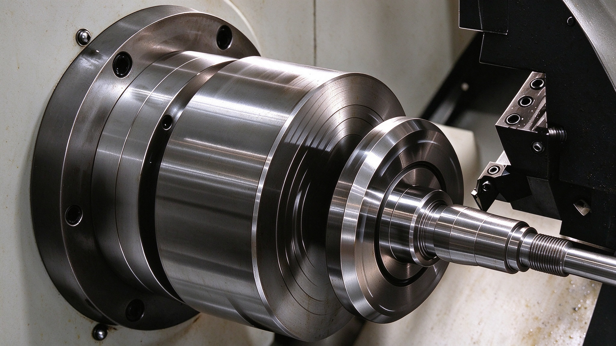
4. Core Selection Criteria for Automation Part Machining Suppliers
For automation equipment manufacturers, machining suppliers are long-term partners, not simple job shops. Selection should not be based on price alone. Three core capabilities deserve close examination.
4.1 Technical Understanding and Communication Capability
A quality supplier understands the assembly logic behind drawings, and proactively identifies critical dimensions and potential risks. They can distinguish between general dimensions and critical fit dimensions, and apply different control levels accordingly.
They can also anticipate machining risks with thin walls, deep grooves, and slender features, and provide practical DFM optimization suggestions. When drawing changes occur, they respond quickly and assess process impacts and lead time adjustments clearly.
4.2 Integrated Machining and Inspection Capabilities
Different parts require different processes and inspection methods. A supplier’s capability coverage directly determines part suitability and production stability.
Evaluate material range first, and whether processing methods for aluminum, carbon steel, and stainless steel are mature. Check whether in-house capabilities cover milling, turning, and surface treatment to reduce subcontracting errors. Also confirm inspection capabilities cover geometric tolerances such as hole position, flatness, and concentricity, not just basic linear dimensions.
4.3 Stable Batch Delivery Capability
Automation equipment generates ongoing spare part and production demand. For repeat orders, batch-to-batch consistency matters more than perfect single parts.
Confirm whether the supplier has a complete quality system covering first article inspection, in-process sampling, and final inspection. Verify their ability to handle repeat orders and ensure dimensional interchangeability across batches. Also assess whether delivery lead times are stable enough to match equipment assembly schedules.
Conclusión
Industrial automation components may be small, but they directly determine overall equipment assembly efficiency, operational accuracy, and service life. Only by taking an assembly-oriented approach and controlling quality across the entire workflow — from prototype validation to process control to mass production — can manufacturers reduce rework and improve efficiency at the source.
PartsMastery has deep expertise in precision machining for industrial automation. With comprehensive in-house CNC milling, CNC turning, and quality inspection systems, we deliver custom component manufacturing tailored to different materials, geometries, and accuracy requirements. We support full project lifecycle delivery from prototype development to batch production, helping automation equipment customers shorten assembly cycles and improve equipment reliability.