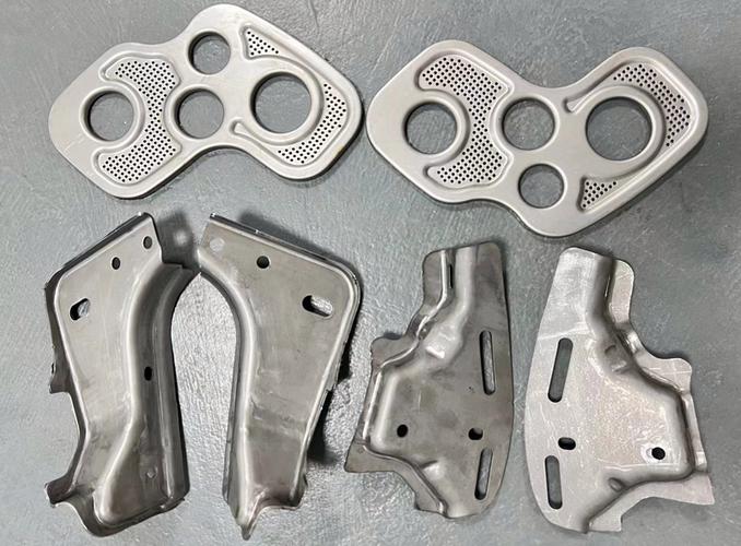
Typical deep drawn sheet metal components
A deep drawn part may look straightforward on a CAD screen. Once the sheet metal enters the press, however, the real challenges begin. An overly sharp punch radius can split the wall, while an unsupported flange area wrinkles without enough blank-holder force.
Engineers should map the material flow path before cutting any tool steel. The draw depth-to-opening ratio sets the overall process complexity. Corner radii and base material properties decide whether strain distributes evenly. In addition, the tolerances on your drawing determine whether one draw suffices, or whether multiple redraws and secondary machining become necessary.
This guide walks through the design screening logic for deep drawn parts. It also shows how early decisions reduce scrap rates and shorten tool tryout cycles.
What Is Deep Drawing, Exactly?
Deep drawing is a sheet metal forming process. A punch pushes a flat blank into a die cavity while a blank holder applies controlled clamping force around the edge. During this action, the blank material contracts radially inward and forms a hollow part — such as a cup, shell, or enclosed housing.
Unlike simple bending, deep drawing moves material across a large area. The part geometry and the sheet’s ductility must accommodate this large-scale deformation. Every working component of the die plays a critical role in guiding that material flow in an orderly way.
Is Your Part a Good Candidate for Deep Drawing?
Deep drawing excels at hollow parts with continuous sidewalls and smooth transitions — cups and enclosures are classic examples. One operation produces a seamless structure, which eliminates welding and joining steps. That said, the process only makes sense when the order volume justifies the dedicated tooling cost.
Generally, a part fits deep drawing well when it has:
A cup, box, or shell-like overall shape
Continuous walls with generous radii at the bottom and corners
A draw depth within a stable, proven range
Few holes, slots, or ribs in high-strain regions
A production volume large enough to amortize tooling costs
You need a closer feasibility review when the draw depth is large relative to the opening, or when sharp cross-section changes exist. Sudden depth variations cause uneven sheet feed. Tight tolerances on large formed surfaces or near the punch radius often require sizing operations or post-machining.
Deep drawing stamping delivers excellent dimensional consistency in high-volume runs. For low to medium volumes, a sheet-metal-fabrication-plus-welding route may cost less if a seam is acceptable. Compare the full process cost, not just the forming price — tool amortization and inspection expenses shift the break-even point.
Start a design-for-manufacturability (DFM) review early, using the CAD model. Your technical drawing should specify sheet thickness, critical control dimensions, and appearance class. Include the estimated volume, and state whether trimming or secondary operations are acceptable.
Core Principles of Geometric Design
Every feature changes how the sheet enters the die and where stress concentrates. Therefore, evaluate geometric parameters as part of a complete forming system rather than checking each dimension in isolation.
Control the Depth-to-Opening Ratio
A deeper part pulls more material into the die, which raises tensile stress. Local thinning becomes more likely, and the sidewall may even split at stress-concentration points.
For round parts, engineers use the draw ratio — blank diameter divided by punch diameter — as an initial screening tool. This number is not an absolute pass-or-fail threshold, however. The material’s metallurgical condition sets the basic forming limit, while die construction and process parameters define what you can consistently achieve in production.
Complex shapes or deep parts may need multiple redraws followed by sizing. If work hardening leaves too little formability for the next stage, an intermediate annealing step may become necessary. Confirm the entire operation sequence before locking in any feature.
Set Practical Punch and Die Radii
The punch radius controls how sharply the sheet bends where the bottom meets the wall. A radius that is too small concentrates stress and triggers cracking. The die-entry radius controls how smoothly the blank flows into the cavity. It must allow steady material movement without losing flange control.
Base the actual values on material type and sheet thickness. If your product demands a very sharp finished corner, you usually reach it through multiple forming steps or a final sizing operation — not by forcing it in the first draw.
Pay Attention to Plan-View Corner Radii
Material flows more uniformly in round parts than in rectangular or irregular shapes. In a rectangular housing, the four corners follow a more complex strain path and usually thin out more severely. Larger corner radii ease this transition. Asymmetric features still require a local flow analysis, though.
Accept That Wall Thickness Will Vary
The blank starts at a uniform nominal thickness, but the formed sidewall will not stay uniform. The punch-radius region typically thins, while areas under compressive flow may thicken slightly. Define a minimum wall thickness only where the function requires it, and verify those zones during first-article inspection. Simply specifying a thicker blank may change the forming behavior without solving the root problem.
Place Holes and Formed Features Carefully
Added features disrupt normal material flow. Holes cut before drawing may stretch or shift during forming, especially near corners or the punch radius. Ribs and embossments transfer stress to the surrounding wall. For critical openings, punch them after drawing whenever possible. Features that need even higher precision can go to CNC machining.
Leave Room for Secondary Operations and Tolerances
Because sheet properties and flow characteristics vary around the part circumference, the final edge height rarely comes out perfectly even. When the rim serves only a functional or decorative purpose, leave enough material for trimming. Apply tight tolerances only to features that affect fit or performance. Your drawing should also clearly mark which surfaces will be pierced, sized, or machined after forming.
Material Selection Strategy
The material’s mechanical properties directly determine how much deformation the blank can absorb before it fails. Poor flow control causes wrinkling, while stress concentration leads to necking or tearing. For selection, the exact grade and temper matter far more than a generic material category.
Ductility and the strain-hardening exponent decide how evenly strain spreads. Plastic anisotropy affects wall thinning and earing. Yield strength influences forming force and springback, while sheet consistency determines process repeatability.
Material Family
Design Advantage
Key Concern
Low-carbon draw steel
Good formability, stable production
Usually needs corrosion protection or coating
Stainless steel
Excellent corrosion resistance, high strength
Strong work hardening, high forming load, fast die wear
Aluminum alloy
Lightweight with good corrosion resistance
Formability varies widely by alloy and temper
Copper & brass
Right grades offer good conductivity and formability
Higher cost, surface quality and work hardening need attention
Never write just “stainless steel” or “aluminum” on the drawing. Specify the exact alloy grade, supply temper, and nominal thickness. Note any special material requirements as well.
For repeat-production projects, also confirm the following:
Acceptable range of mechanical properties
Sheet thickness tolerance
Rolling direction requirements
Surface roughness and appearance grade
Material certification needs
Lubricant and cleanliness restrictions
A substitute material may meet the strength spec yet behave very differently in the die. A different temper changes ductility, and a new coating can alter the friction coefficient. Any such change should trigger a fresh formability review.
Tooling and Process Considerations
Review the deep drawing die alongside the product design. Even a theoretically feasible CAD model can fail in production if blank control or die construction is flawed.
Punch, Die, and Running Clearance
The punch defines the internal shape, while the die controls the external flow path. Their radii set how much the sheet changes direction. Alignment and clearance affect wall thinning and dimensional repeatability. The working surfaces of the die must also be smooth enough to prevent galling and erratic friction.
Blank Holder and Draw Beads
The blank holder stops the flange from folding as it enters the cavity. Too little pressure causes wrinkles. Too much restraint, on the other hand, tears the material near the punch radius. Draw beads provide extra local control when feed rates differ across zones. The flange design must leave enough space for both features.
Lubrication and Die Surface Treatment
Lubricant directly governs the friction between sheet and die. Poor lubrication increases the forming force and can score the surface. Choose the lubricant based on material characteristics, appearance requirements, and downstream cleaning. For materials prone to adhesive wear, die surface treatment and routine maintenance are equally important.
Forming Sequence and Blank Development
Shallow parts may form in a single operation. Deeper shapes often need one or more redraws, followed by trimming and piercing. A sizing operation can push critical geometry closer to target. Every added station raises tooling cost — and introduces another quality checkpoint to monitor.
Blank shape matters just as much. A poorly developed blank leaves excess flange material or produces uneven edges. For non-round parts, you usually refine the blank outline through trials or forming simulation.
Before approving the tooling plan, clarify these questions:
How many forming stations do you expect?
Which features come from forming, trimming, piercing, or machining?
Do you need intermediate annealing or final sizing?
Which dimensions are process-critical?
What will first-article inspection focus on?
Common Defects and Fixes
Deep drawing defects rarely stem from a single variable. Start with geometry and material, because they define the basic forming window. Then check blank shape and lubrication to judge whether the material feeds normally. Evaluate die condition and press settings within the same framework.
Defect
Likely Cause
Design or Process Fix
Flange or wall wrinkling
Excess material, low blank-holder force, or lack of local support
Adjust blank size, flange geometry, holder force, or draw-bead layout
Tearing or splitting
Small radius, excessive draw, high restraint, or limited ductility
Increase radius, reduce per-stage draw, improve lubrication, or add annealing
Excessive local thinning
Strain concentration near corners or transitions
Smooth transitions, redistribute depth, or reorder operations
Earing
Anisotropy from sheet rolling direction
Control material orientation, compensate blank shape, and allow trimming
Uneven rim height
Uneven flow, anisotropy, or poor blank shape
Optimize blank size and leave adequate trim allowance
Springback
Elastic recovery and uneven residual stress
Use over-draw compensation, sizing, or wider functional tolerances
Surface scratches or scoring
High friction, debris, rough contact, or poor lubrication
Check die surface finish, lubricant plan, maintenance, and handling
Distorted holes or slots
Feature in high-strain zone or premature piercing
Relocate feature or pierce after drawing is complete
Keep in mind that press adjustments cannot always overcome geometric limits. The more robust solution is often a design change itself — enlarging a radius or moving a hole, for instance. When a non-critical tolerance forces an unnecessary sizing step, relaxing that tolerance is also a practical move.
Key Takeaways
A successful deep drawn part gives the material a controlled flow path into the die. Overall draw depth and corner geometry set the basic route, while the material condition sets the deformation ceiling. Feature placement and tolerance choices should all serve the same forming strategy.
The first task in a design review is deciding whether a single draw is enough. If not, the supplier should spell out the additional forming stations. Next, assign trimming and piercing to the right positions in the sequence. Reserve sizing or post-draw machining for features that genuinely need tighter precision. Finally, make sure the production volume supports the chosen tooling investment.
PartsMastery offers sheet metal fabrication and stamping services, including design-for-manufacturability (DFM) reviews plus downstream finishing or assembly. To start a manufacturability assessment, send your CAD model or a drawing with material specs and estimated volume, and clearly mark critical tolerances and surface finish requirements.
Frequently Asked Questions
When is deep drawing more economical than welding and machining?
Deep drawing becomes attractive when the volume is large enough to spread the tooling cost across many parts. A seamless housing also reduces welding and finishing work. Conversely, other process routes may cost less when volumes are low, designs change often, or a seam is acceptable. Compare the full process cost, including tooling and all secondary operations.
What information do you need to quote a deep drawn part?
Provide a CAD model and a controlled engineering drawing. Clearly state the material grade, temper, and sheet thickness. The supplier also needs the estimated volume and the function-critical dimensions. Mention any wall-thinning limits or exposed-surface requirements. Note on the drawing whether seams and trimming are allowed.
Can I pre-cut holes and slots before drawing?
Yes, when the feature sits in a low-strain area and some deformation is acceptable. Holes near the punch radius stretch more easily, and features near corners or wall transitions may shift as the material flows. For critical openings, piercing after the draw usually gives better dimensional control.
How do you validate a design before approving production tooling?
Start with a DFM review that analyzes expected material flow and draw severity. Forming simulation helps with complex geometry, but physical tryout remains essential. Measure wall thickness and edge height on test pieces. Inspect for cracks or wrinkles, and confirm surface quality and critical dimensions before approving production.