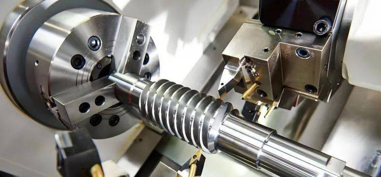
Material cost is a core component of CNC turning part manufacturing costs. This matters especially when machining stainless steel, copper alloys, titanium alloys, aluminum alloys, and high-strength alloy steels. Indeed, high raw material prices mean every excess cut, every defective part, and every unusable remnant directly erodes profit margins.
The programmable and digital nature of CNC turning provides a technical foundation for reducing material waste. You can optimize blank sizes, control machining allowances, streamline tool paths, improve first-pass yield, manage tool life, and recycle scrap. Overall, every stage offers quantifiable cost-reduction potential. This article outlines seven optimization directions and gives manufacturers an actionable roadmap for improving material utilization.
1. Blank Size Optimization: Cutting Waste at the Source
Blank size is the first checkpoint that determines material utilization. If the bar diameter or length far exceeds the finished part, subsequent machining must remove more excess material. This simultaneously increases cutting time and chip volume. In batch production, even a tiny per-unit material loss adds up. Multiply it by hundreds or thousands of units, and you get substantial cumulative cost loss.
You should determine blank dimensions by considering finished part size, machining allowance, fixturing requirements, and subsequent operations. Essentially, the essence of blank size optimization is simple. Minimize unnecessary material consumption before machining begins. Ultimately, this lays the foundation for efficient turning production.
1.1 Precise Bar Diameter Selection
CNC turning typically uses round bars as raw material. Specifically, bar diameter directly determines how much material you must remove radially. If the finished outer diameter is small but you consistently use a much larger bar, the roughing stage generates a large volume of unnecessary chips.
Follow these principles when selecting bars. Choose bar specifications based on the maximum outer diameter of the part. Prioritize standard sizes close to the finished diameter. Reduce unnecessary radial machining allowance. Unify purchasing according to standard material specifications. Standardize bar sizes for batch production. Control the variety of material specifications in inventory.
Overall, an appropriate bar diameter reduces roughing time and chip volume. It also lowers tool load. When machining expensive materials, reducing unnecessary cutting volume directly translates to lower material consumption costs.
Metal bar raw materials sorted by specification in storage — precise selection is the first step in reducing waste
1.2 Lean Cut Length Calculation
Bar length also affects material utilization. When machining short parts, excessive clamping length and overly large cut-off allowance produce a significant amount of unusable remnant. Therefore, calculate cut length precisely based on fixturing requirements, clamping length, cut-off blade width, facing allowance, and finished part length.
A reasonable cut length lets each bar yield more parts while reducing remnants. For batch production, establish standardized cut lengths based on actual part dimensions. As a result, this helps operators follow uniform cutting specifications and reduces manual measurement errors.
Machining allowance directly determines the volume of raw material you must remove during turning. Excessive allowance increases roughing time, tool wear, and chip generation. Insufficient allowance may fail to completely remove blank surface defects. Consequently, this makes it difficult to achieve final dimensional requirements.
Determine appropriate machining allowance based on material condition, blank precision, part size, tolerance requirements, and machine accuracy. For precision-drawn, forged, or high-quality bars, you can typically reduce allowance. For blanks with larger surface or dimensional deviations, you may need to increase it. You should also distribute allowance rationally between roughing and finishing in CNC programs. Typically, roughing removes most excess material. Meanwhile, finishing removes only what is needed to achieve final dimensions and surface quality.
2.1 Rational Roughing Allowance Setting
The goal of roughing is to remove excess material efficiently. But maximum cutting depth is not always the optimal approach. Excessive cutting depth increases tool load. Instead, it causes vibration, chipping, or even workpiece deformation. This in turn affects subsequent finishing. Select an appropriate cutting depth based on material hardness, machine rigidity, and tool performance. Ultimately, this achieves a balance between material removal efficiency and machining stability.
Key control points include the following. Set reasonable cutting depth. Control total roughing allowance. Reduce repeated passes. Lower tool load. Suppress machining vibration. Improve material removal efficiency. Overall, stable roughing removes most excess material quickly. It also reduces scrap caused by machining abnormalities.
Spiral chips generated during turning — rational allowance control effectively reduces chip volume
2.2 Consistent Finishing Allowance Management
Finishing does not need to remove large amounts of material. Rather, its core objective is to achieve final dimensions and surface quality. Excessive finishing allowance increases machining time and tool wear. Insufficient allowance may leave roughing marks incompletely removed. Maintain consistent allowance after semi-finishing. As a result, this lets the finishing tool remove a predictable amount of material, reducing unnecessary machining passes.
Uniform finishing allowance helps maintain stable cutting conditions and consistent tool loads. Consequently, this improves surface quality and dimensional consistency. For precision parts, stable allowance management reduces rework and scrap. Thus, it indirectly lowers material waste.
3. CNC Program Optimization: Reducing Air Cuts and Repeated Passes
CNC programs determine the final dimensions of a part. They also directly affect material consumption and machining time. Efficient tool paths reduce air cuts, repeated cutting, and unnecessary tool movements. Accordingly, this allows the tool to machine target areas more directly.
For simple shaft parts, you can optimize rough turning cycles to reduce repeated movements. For parts with steps, grooves, and threads, arrange tool paths rationally according to machining sequence. This minimizes unnecessary tool retraction and repositioning. Program optimization also prevents the tool from repeatedly cutting already machined areas, thereby reducing tool wear and unnecessary chip generation. Use CNC simulation software to verify programs before production. Specifically, it identifies repeated paths or inefficient movements.
3.1 Eliminating Air Travel and Repeated Cutting
Tool movement without removing material does not directly consume material. But it increases machining time. It may also cause the tool to produce unnecessary friction over already machined areas. Optimize program paths so the tool travels shorter distances within safe operating ranges, thereby reducing ineffective travel.
Specific optimization directions include the following. Shorten tool travel distance. Reduce repeated machining. Optimize retraction paths. Arrange machining sequence rationally. Compress air-cut time. Reduce tool wear. Efficient program paths ensure every cutting action has a clear purpose. They also reduce unnecessary material removal.
3.2 Applying Standardized Machining Cycles
Modern CNC systems typically provide multiple turning cycles. These cover external turning, internal boring, facing, threading, and other operations. Proper use of these cycles reduces repetitive programming. It also enables the tool to move along stable machining paths. For batch production, you can develop standardized program templates for common part structures, thereby reducing programming errors.
Once you stabilize a program, it also reduces dimensional variation between parts. Consequently, this minimizes scrap and material loss caused by programming errors.
4. First-Pass Yield Improvement: Defective Parts Are the Greatest Waste
Material waste comes from chips and remnants. It also comes, significantly, from defective parts. If you scrap a part due to dimensional deviation, thread error, surface defect, or machining deformation, all the raw material invested in that part is lost. Therefore, improving first-pass yield requires systematic control. You must control program verification, tool management, fixture positioning, cutting parameters, and in-process inspection.
Indeed, this is especially critical when machining expensive materials. A single defective part can cause significant economic loss. First-article inspection, critical dimension sampling, and in-process measurement detect machining trend shifts early. They prevent large numbers of parts from developing the same defects.
4.1 First-Article Inspection System
After batch production begins, inspect the first part comprehensively. Confirm that the program, tool offsets, and fixturing conditions all meet production requirements. Begin continuous machining only after the first article passes verification. This reduces the risk of batch scrap caused by program errors or dimensional deviations.
First-article inspection should cover the following. Outer diameter dimensions. Inner bore dimensions. Overall part length. Groove width and depth. Thread parameters. Surface quality. Critical tolerance confirmation. First-article inspection detects problems when material consumption is still very low. Thus, this makes it a key means of controlling batch material waste.
A quality inspector performing precision dimensional measurement on a turned part using a digital caliper
4.2 In-Process Dimensional Monitoring
During continuous turning, tools gradually wear. Machine temperature also changes. Both factors can lead to dimensional deviation. Use regular sampling or in-line measurement to detect dimensional trend changes. Accordingly, this allows timely adjustment of tool offset values.
Timely dimensional correction prevents the production of large numbers of nonconforming parts, thereby reducing rework and scrap. For high-precision automated production lines, in-process inspection systems collect critical dimensional data automatically. This further improves process control efficiency.
5. Tool Life Management: Preventing Abnormal Scrap
Tool condition directly affects material removal quality. When a tool wears excessively, cutting resistance increases. Consequently, surface quality declines. Furthermore, part dimensions may gradually shift. If a tool suffers chipping or unexpected failure, severe surface defects may appear. Ultimately, this can even lead to direct part scrappage.
Establish a tool life management system. This lets manufacturers set reasonable replacement standards based on machining volume, cutting time, and actual tool wear. Different materials require inserts with appropriate substrate and geometry, thereby maintaining stable cutting conditions. Effective tool management reduces abnormal machining and unexpected scrap. It also extends tool service life.
5.1 Material-Tool Matching Principles
Aluminum alloys, copper alloys, stainless steel, carbon steel, alloy steel, and engineering plastics all have different cutting characteristics. Do not machine them with the same tool configuration. Select tools based on material hardness, toughness, and thermal conductivity, thereby reducing cutting resistance and abnormal wear.
Matching key points include the following. Use sharp tools for aluminum alloys. Prioritize smooth chip evacuation for copper alloys. Select wear-resistant tools for stainless steel. Choose stable-cutting tools for carbon steel. Use high-strength tools for alloy steel. Control cutting heat for engineering plastics. Correct material-tool matching reduces abnormal tool damage. Furthermore, it improves machining stability. It also lowers material scrap caused by tool-related issues.
5.2 Data-Driven Tool Life Management
Record tool usage time, machining volume, material type, and wear condition. As a result, this helps manufacturers establish reasonable tool replacement cycles. Do not replace tools only after complete failure. Do not discard them prematurely while they still perform effectively.
Use production data to establish more accurate tool life standards. This enables operators to schedule tool replacements based on actual machining conditions, thereby reducing unexpected quality issues and material loss.
6. Remnant and Chip Recycling: Unlocking End-of-Life Value
Offcuts and remnants from CNC turning are not all worthless scrap. You can reuse some offcuts of suitable length and good surface condition for manufacturing short parts. Additionally, manufacturers can establish offcut classification and storage procedures. Specifically, sort by material type, specification, and length for future production use.
Some materials cannot be reused. Examples include copper, aluminum, stainless steel, and titanium alloys. Sort and process these through appropriate metal recycling channels to recover material value. Overall, rational use of offcuts reduces raw material purchasing requirements. It also lowers waste disposal costs.
6.1 Offcut Classification and Reuse
Never mix offcuts of different materials. Label all of them. Classify them by material, diameter, length, and condition. As a result, clear labeling enables production personnel to quickly find offcuts suitable for the current order.
Management key points include the following. Sort by material. Group by diameter. Categorize by length. Mark remaining quantity. Record storage date. Prioritize usable remnants. Ultimately, standardized remnant material management improves material reuse rates. It reduces the need to purchase full bars for short parts.
Metal chips and scrap sorted by material for recycling — standardized recovery significantly improves resource utilization
6.2 Metal Chip Separation and Recycling
Metal chips from turning have recycling value. Collect chips of different materials separately. Indeed, mixing aluminum, copper, stainless steel, and steel chips increases subsequent recycling difficulty. It may also reduce recovery value.
Classified collection and standardized storage enable more effective waste recovery. They also keep the machining area cleaner and more organized.
7. Automation and Digitalization: A Closed Loop for Continuous Optimization
Automation reduces errors caused by manual operation. Furthermore, it makes material utilization more stable. Automated loading and unloading equipment clamps and unloads workpieces according to preset programs, thereby reducing inconsistency in manual loading dimensions. Automated inspection systems continuously monitor critical dimensions. They issue warnings or stop the machine when they detect abnormalities, thereby preventing large volumes of material from continuing through incorrect machining.
Intelligent production systems also record key data for each batch. They track material consumption, accepted part quantity, scrap quantity, and remnant volume. Accordingly, this provides data support for purchasing and process optimization. For high-volume CNC turning, automated management makes material usage more transparent. Furthermore, it helps manufacturers continuously identify waste-reduction opportunities.
7.1 Automated Cutting and Loading/Unloading
Automated cutting equipment repeatedly cuts bars according to preset lengths, thereby reducing errors caused by manual measurement. For parts of the same specification, standardized cutting programs ensure consistent length for every bar.
Moreover, automated cutting increases production speed. It also reduces offcut waste caused by excessive cut lengths. Ultimately, for mass production, these cost savings grow increasingly significant as output increases.
7.2 Production Data-Driven Material Control
Digital production management systems record material purchasing, actual consumption, production quantity, scrap quantity, and remaining material. Long-term data analysis reveals actual material utilization rates for different parts. It also identifies abnormal consumption. Manufacturers can use historical data to optimize purchasing specifications and blank sizes, thereby reducing inventory backlog and improving material turnover efficiency.
Conclusion
In CNC turning, reducing material waste requires continuous optimization across multiple areas. Specifically, you must optimize blank specifications, cut lengths, machining allowances, program paths, tool condition, quality inspection, remnant management, and automated production. Select bars with dimensions close to the finished part, thereby reducing roughing material removal. Rationally plan machining allowances to reduce repeated cutting. Optimize CNC programs to reduce unnecessary tool movement and material consumption. Strengthen first-article and in-process inspection to reduce batch scrap. Use effective tool life management to prevent material loss from tool abnormalities. Standardize remnant and chip recycling to further improve resource utilization.
For precision CNC machining enterprises working with high-value metals, material utilization matters beyond manufacturing costs. It also affects long-term production efficiency and resource management standards. Through continuous improvement of machining processes and production management, every bar, every blank, and every batch of material can create greater value. Ultimately, this approach enables manufacturers to reduce production waste while maintaining part precision and product quality. It improves the overall economic efficiency of CNC turning operations.
At PartsMastery, we provide precision CNC turning and comprehensive surface finishing services for custom metal parts. Specifically, we help customers effectively control material consumption, machining quality, dimensional accuracy, and production efficiency. This meets demanding engineering application requirements.